
Buffering and energy dissipation collision avoidance device of bridge

A technology of anti-collision device and buffer device, which is applied in the direction of bridges, bridge parts, bridge construction, etc., and can solve problems such as bridge collision, ship driving deviation or deflection, etc.

Inactive Publication Date: 2014-12-31
杨光华
View PDF6 Cites 6 Cited by
  • Summary
  • Abstract
  • Description
  • Claims
  • Application Information

AI Technical Summary

Problems solved by technology

[0007] At present, most of the bridge frames of the bridges in rivers, lakes and seas are arc-shaped bridge frames. When the ship passes the bridge hole, the top of the ship is higher than the height of the bridge and collides with the bridge frame; drifted or deflected, causing the ship to hit the bridge frame

Method used


Image

  • Buffering and energy dissipation collision avoidance device of bridge
  • Buffering and energy dissipation collision avoidance device of bridge
  • Buffering and energy dissipation collision avoidance device of bridge

Examples


Embodiment 1

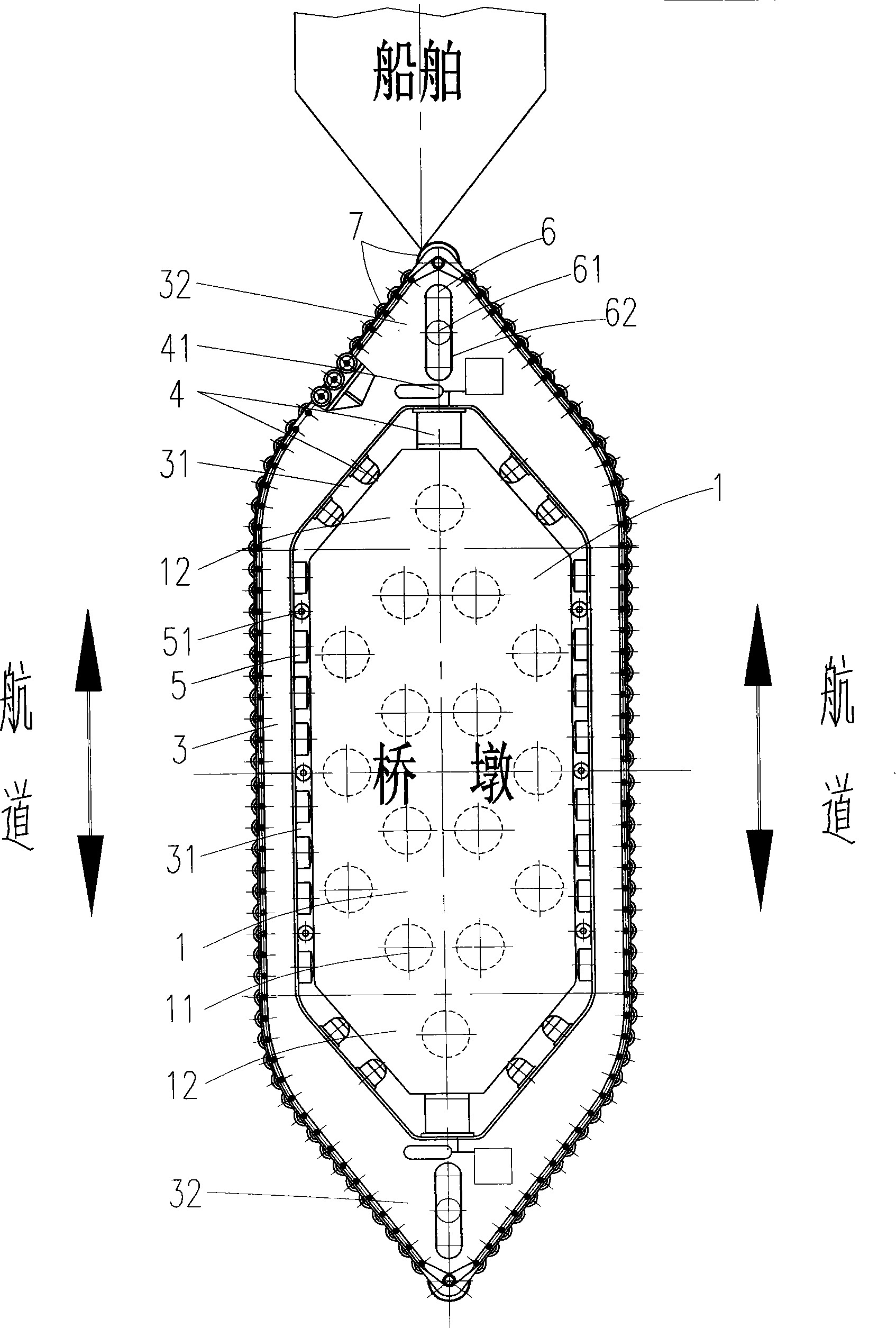
[0037] like figure 1 As shown, the anti-collision device used for the buffering and energy dissipation of the bridge of the pier 1 includes an anti-collision frame 3 with a long chute 31 set on the periphery of the pier cap 12 of the bridge, the anti-collision frame 3 and the pier cap Buffer 4 is arranged between the two heads of 12, and buffer device 5 is arranged between the two sides of the anti-collision frame 3 and the pier cap 12, and the two ends of the anti-collision frame 3 present a streamlined head 32 or a mountain-shaped Head 32, wherein the bridge pier 1 is composed of pile foundation 11 and cap 12, wherein the long chute 31 on the anti-collision frame 3 is: the length of the chute 31 is greater than the length of the pier cap 12, in the chute There is enough space between 31 and the pier cap 12 to set the buffer 4, and the anti-collision frame 3 compresses the buffer 4 to do work under the action of external force, and the long chute 31 of the anti-collision fram...

Embodiment 2

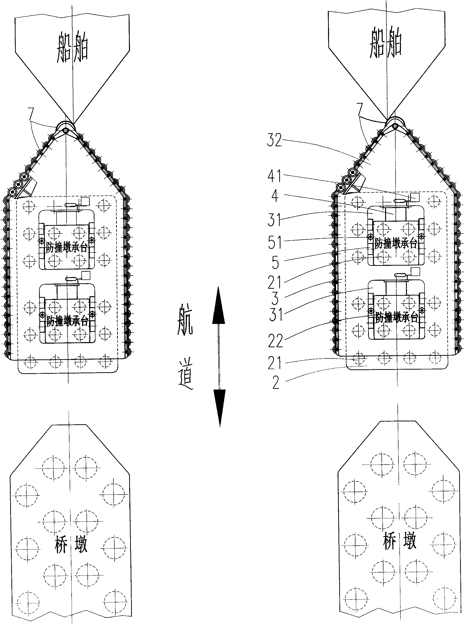
[0044] like figure 2 As shown, the anti-collision device used for the buffering and energy dissipation of the bridge in the form of anti-collision pier 2 includes setting anti-collision pier 2 on both sides of the waterway in the water area in front of the bridge, and the outer periphery of the cap 22 of the anti-collision pier 2 is equipped with a The anti-collision frame 3 of the chute 31 is arranged with a buffer 4 between the long chute 31 of the anti-collision frame 3 and the two ends of the platform 22 of the anti-collision pier 2, and the long chute 31 on the anti-collision frame 3 Between the two sides of the bearing platform 22 of the anti-collision pier 2, a buffer device 5 is arranged, and one end of the anti-collision frame 3 facing the waters presents a streamlined head 32 or a head 32 of a mountain-shaped slope, wherein the bridge anti-collision The bumper pier 2 is composed of a pile foundation 21 and a cap 22, wherein, in the embodiment, two caps 22 are set at...

Embodiment 3

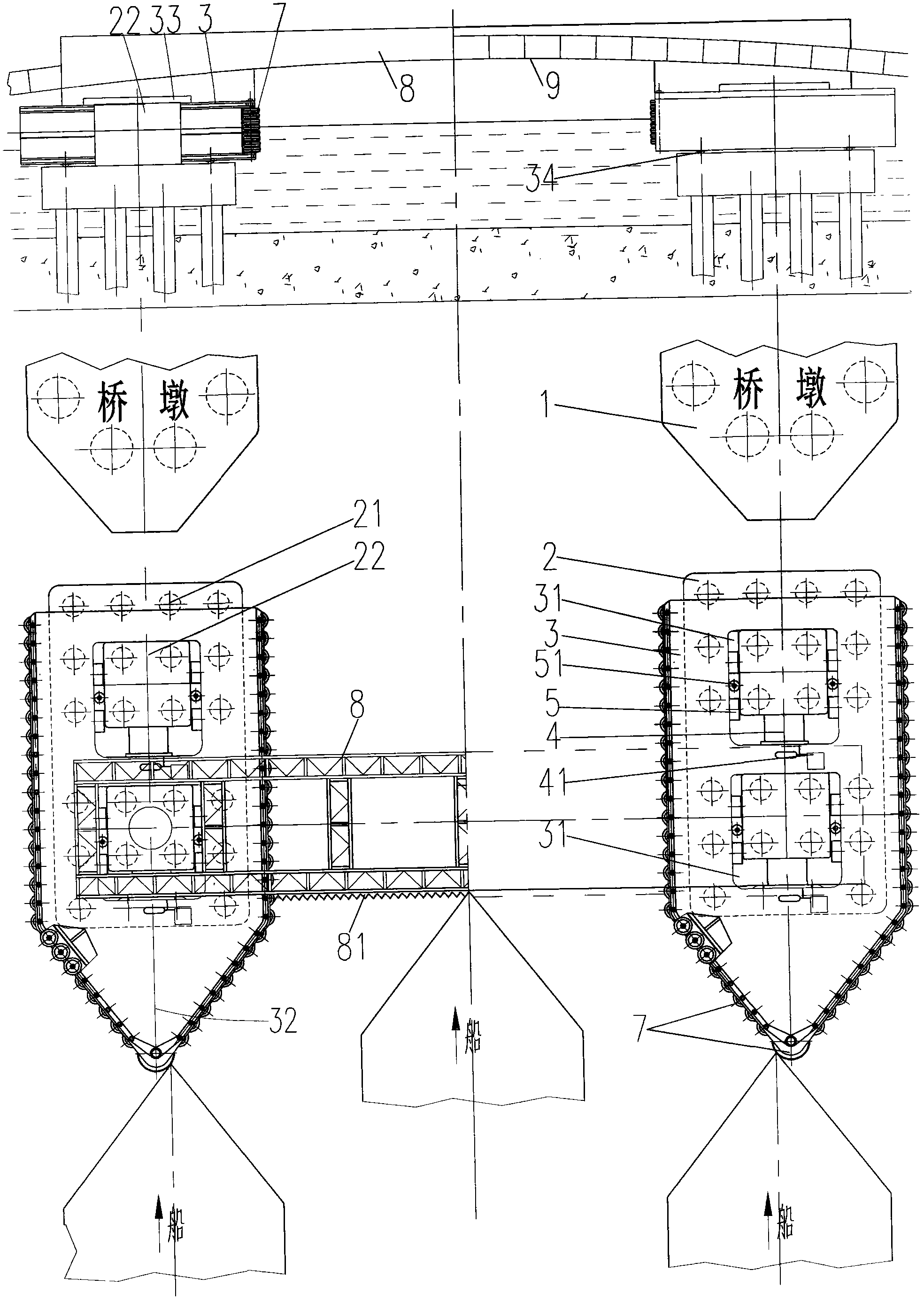
[0047] like image 3 As shown, the anti-collision device for the height limit buffering and energy dissipation of the bridge frame 9 in the form of the anti-collision pier 2 includes setting the anti-collision pier 2 on both sides of the waterway in the water area in front of the bridge, and setting the anti-collision pier 2 on the periphery of the cap 22 of the anti-collision pier 2 The anti-collision frame 3 with the long chute 31 is set, and the buffer 4 is arranged between the long chute 31 of the anti-collision frame 3 and the two ends of the platform 22 of the anti-collision pier 2, and the anti-collision frame 3 A buffer device 5 is arranged between the long chute 31 and the two sides of the platform 22 of the anti-collision pier 2, and one end of the anti-collision frame 3 facing the waters presents a streamlined head 32 or a mountain-shaped inclined-plane head 32, On the anti-collision frame 3 on both sides of the waterway, an anti-ship height-limiting frame 8 is set....


PUM


Abstract

The invention relates to a buffering and energy dissipation collision avoidance device for a bridge. The buffering and energy dissipation collision avoidance device comprises a collision avoidance structure which sleeves the periphery of a bearing platform of a pier or a collision avoidance pier or a channel pier of the bridge and is provided with a long sliding chute, wherein buffers are distributed between the long sliding chute of the collision avoidance structure and two ends of the bearing platform of the pier or the collision avoidance pier or the channel pier; buffering devices are distributed between the long sliding chute of the collision avoidance structure and two sides of the bearing platform of the pier or the collision avoidance pier or the channel pier; the head of the collision avoidance structure is a streamline-shaped head or a leftwards inverted E-shaped head; height limiting frames for preventing ship collision are arranged on the collision avoidance structure in front of the bridge and on two sides of a channel. The buffering and energy dissipation collision avoidance device for the bridge has the technical advantages that when a ship collides with the head of the collision avoidance structure and the height limiting frames for preventing ship collision, the long sliding chute of the collision avoidance structure moves to press the buffers to do work to dissipate kinetic energy of the ship; meanwhile, under the guide of a leftwards inverted E-shaped slope or a streamline-shaped guide surface at the head of the collision avoidance structure, the ship is subjected to deviation rectification, and the height limiting frames stop a superhigh ship and protect a bridge frame of the bridge; when the side of the ship collides with the collision avoidance structure, the buffering devices on the long sliding chute of the collision avoidance structure protect the pier or the collision avoidance pier.

Description

technical field [0001] The invention relates to the technical field of bridge ship collision protection, in particular to a bridge pier, a bridge anti-collision pier and a bridge frame ship collision protection device. Background technique [0002] With the continuous development of the transportation industry, a large number of cross-sea and cross-river bridges are constantly being built. Most of the rivers and seas where such bridges are located are busy waterways, and the conditions such as currents, waves, wind and waves are complicated, and the bridge inevitably bears a certain risk of ship collision. In non-conditions, when a ship rubs or hits a bridge pier or bridge frame, the momentum of a ship with a certain speed is very large. According to the momentum theorem: mv1-mv2=FΔt, Δt is instantaneous, so its impact force is huge , Damaged bridges occur from time to time. [0003] At present, the forms of anti-collision devices for ships hitting bridges can be divided i...

Claims


Application Information

Patent Timeline
IPC IPC(8): E02B3/26E01D19/02
CPCY02A30/30
Inventor 杨光华
Owner 杨光华
Learn More