
Method for operating a microcomputer apparatus

A technology of microcomputer and equipment, applied in the field of running microcomputer equipment, can solve the problems such as the micro-controller no longer responding, the module cannot be freely configured, and the threshold voltage to be monitored is roughly adjusted.

Inactive Publication Date: 2014-12-31
ROBERT BOSCH GMBH
View PDF5 Cites 0 Cited by
  • Summary
  • Abstract
  • Description
  • Claims
  • Application Information

AI Technical Summary

Problems solved by technology

Disadvantageously, however, the modules are generally not freely configurable, so that the threshold voltages to be monitored are often not, or only very roughly, or depending on the voltage supply, adjustable with the aid of the modules
Said modules usually switch the microcontroller into a reset state, so that the microcontroller can no longer react properly afterwards

Method used


Image

  • Method for operating a microcomputer apparatus
  • Method for operating a microcomputer apparatus

Examples


Embodiment Construction

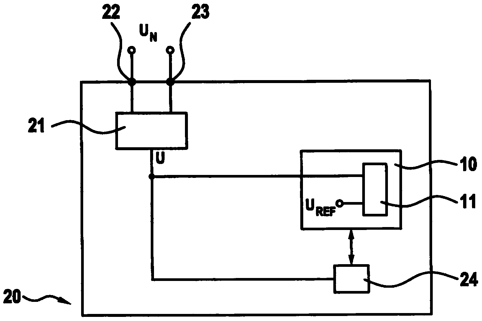
[0026] figure 1 An embodiment of an electrical device 20 according to the invention is shown. It can be seen that the electrical equipment 20 has a first connection end 22 and a second connection end 23, through which the electrical equipment 20 can be connected to, for example, a 110V or 220V power supply with 50Hz or 60Hz. AC voltage U N superior. The electric device 20 also includes a power supply unit 21 which converts the grid voltage U N This is transformed into a supply voltage U with a DC voltage level of, for example, 5V. It is possible that the power supply unit 21 generates varying voltage levels under varying grid conditions, so that a disadvantageously not always the desired stable voltage of 5 V is available at the output of the power supply unit 21 .

[0027] Microcomputer device 10 (for example microcontroller, microprocessor, etc.) and electronics 24 are powered with supply voltage U. The electronic device 24 can be designed, for example, as a device for ...


PUM


Abstract

A method for operating a microcomputer apparatus includes provisioning an electrical reference voltage(UREF) that is independent of an electrical supply voltage(u), continuously comparing a defined level(p) of the electrical reference voltage(UREF) with the electrical supply voltage(u), and performing a defined operation with the microcomputer apparatus for at least one defined ratio between the defined level of the electrical reference voltage and the electrical supply voltage. The provisioning and the continuous comparing involves using a functional module (11) of the microcomputer apparatus.

Description

technical field [0001] The invention relates to a method for operating a microcomputer device. The invention also relates to an electrical device with mains voltage supply. Background technique [0002] For electrical installations supplied with AC voltage by means of phase cut-in control (Phasenanschnittsteuerung), the synchronization signal is the digital image (Abbild) of the AC voltage signal and is therefore an important signal because it is predetermined for generating and processing the electrical Clock pulses for additional signals of the device. [0003] It is already known that the electronics of such devices can be brought into a safe state in the event of an excessively low supply voltage. For this purpose, it is possible, for example, to use so-called brown-out modules, which are integrated in several microcontrollers. However, it is disadvantageous that the modules are generally not freely configurable, so that the threshold voltage to be monitored is usuall...

Claims


Application Information

Patent Timeline
IPC IPC(8): G06F1/28
CPCB25F5/00G01R19/16533G01R19/16576G01R19/165
Inventor D·龙巴赫K·波戈热尔斯基J·维什涅夫斯基M·普兰特纳
Owner ROBERT BOSCH GMBH
Learn More