Adjustable splicing mould bed

An adjustable tire frame technology, applied in auxiliary devices, auxiliary welding equipment, welding/cutting auxiliary equipment, etc., can solve the problems of inability to use the tire frame and adjust the tire frame, and achieve the effect of easy disassembly

Active Publication Date: 2015-01-07
JIANGSU VOCATIONAL INST OF ARCHITECTURAL TECH
View PDF7 Cites 15 Cited by
  • Summary
  • Abstract
  • Description
  • Claims
  • Application Information

AI Technical Summary

Problems solved by technology

[0003] The invention provides an adjustable assembled tire frame, the joints of the parts are connected by bo

Method used


Image

  • Adjustable splicing mould bed
  • Adjustable splicing mould bed
  • Adjustable splicing mould bed

Examples


Embodiment Construction

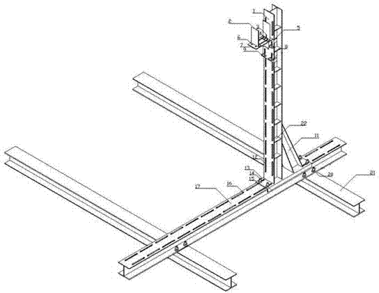
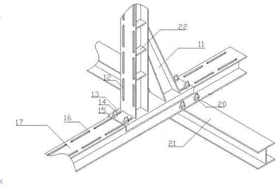
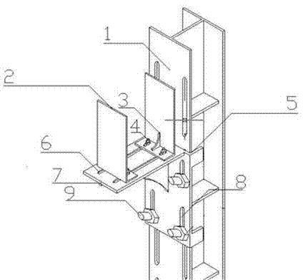
[0015] An adjustable assembled tire frame, the I-steel platform (21) is connected to an I-steel crossbar (17) through bolts (20), and the I-steel crossbar (17) is connected to a Root I-shaped steel pole (1), the back of channel steel I (15) is welded with the vertical pole (1), and the front of channel steel I (15) is stuck on the I-beam cross bar (17) with a notch. There are several oblong holes (16) on the beam cross bar (17), four oblong holes (13) are arranged on the channel steel I (15), and the oblong holes (16) of the I-beam cross bar (17) Length is 20cm, and the distance between every two oblong holes (16) is 5cm, and the length of the oblong hole (13) of channel steel I (15) is 6cm, utilizes the oblong hole ( 16) to change the lateral size of the tire frame. When adjusting the lateral size of the tire frame, unscrew the nut of the bolt (14), adjust the position of the screw in the bolt hole, and tighten the nut to fix the size after adjustment. The adjustable size in...


PUM

PropertyMeasurementUnit
Lengthaaaaaaaaaa
Lengthaaaaaaaaaa
Lengthaaaaaaaaaa

Abstract

Provided is an adjustable splicing mould bed. An I steel platform is connected with an I steel cross bar through a bolt, the I steel cross bar is connected with an I steel vertical bar through groove steel I, the back of the groove steel I is welded with the I steel vertical bar, the front of the groove steel I is clamped on the I steel cross bar through a slot, a plurality of long round holes are formed in the I steel cross bar and the groove steel I, a cantilever plate is arranged on one side of the inner side of the I steel vertical bar, the cantilever plate is connected with the I steel vertical bar through groove steel II, the back of the groove steel II is welded with the cantilever plate, the front of the groove steel II is connected with the I steel vertical bar through a bolt, a plurality of long round holes are formed in the I steel vertical bar and the groove steel II, two clamping plates are arranged on the cantilever plate, the bottoms of the clamping plates are connected with the cantilever plate through the bolts, and a plurality of long round holes are formed in the cantilever plate. The size of the mould bed can be changed freely by adjusting the bolts to meet the requirement for assembly of mould beds of different sizes. The mould bed is convenient to disassemble and capable of being used in circulation.

Description

technical field [0001] The invention relates to a tire frame, in particular to an adjustable assembled tire frame. Background technique [0002] With the development of the national economy, there are more and more steel structure buildings. As one of the steel structure buildings, the pipe truss structure is widely used and the number is increasing because of its advantages of large span, light weight, high strength and good earthquake resistance. However, the pipe truss structure cannot be transported to the construction site after being assembled in the factory because of its relatively large span. Therefore, the pipe truss structure is to transport the cut steel pipes to the construction site for on-site assembly and welding. During on-site welding, in order to ensure that the size and position of the welding are correct, the steel pipes are placed on the tire frame for welding. However, since the support frames on the site are temporarily assembled and welded by usin...

Claims


Application Information

Patent Timeline
IPC IPC(8): B23K37/04E04G21/00
CPCB23K37/053E04G21/00
Inventor 戚豹白飞蒋晶晶刘菁菁康文梅
Owner JIANGSU VOCATIONAL INST OF ARCHITECTURAL TECH
Why Eureka
Try Eureka