Concrete prefabricated wall body and vertical pouring hole remaining method thereof

A prefabricated wall and concrete technology, applied in the direction of walls, buildings, building components, etc., to achieve the effect of reducing the total weight and simple operation

Inactive Publication Date: 2015-01-07
CHINA 22MCC GROUP CORP
View PDF5 Cites 6 Cited by
  • Summary
  • Abstract
  • Description
  • Claims
  • Application Information

AI Technical Summary

Problems solved by technology

[0003] The present invention aims to solve the above-mentioned problems existing in the installation of existing prefabricated shear walls, and

Method used


Image

  • Concrete prefabricated wall body and vertical pouring hole remaining method thereof
  • Concrete prefabricated wall body and vertical pouring hole remaining method thereof
  • Concrete prefabricated wall body and vertical pouring hole remaining method thereof

Examples


Embodiment 1

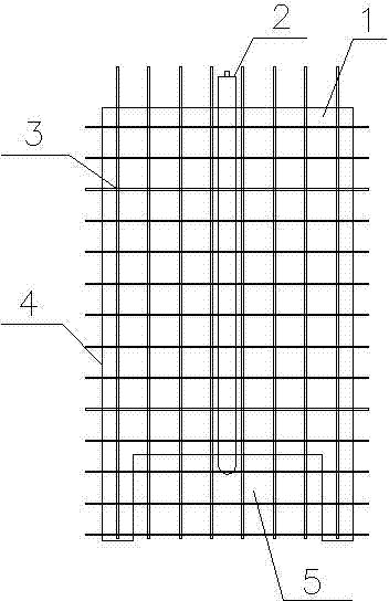
[0022] see figure 1 , the width of the wall body 1 of the prefabricated concrete shear wall is 1600mm, the outriggers are removed, and the cast-in-place section width L=1200mm is reserved for the overlapping parts of the steel bars at the bottom, and a rubber mandrel 2 is placed in the middle part of the wall reinforcement cage 3, Reserve a vertical pouring hole that corresponds to the cast-in-place section 5 and penetrates up and down.

Embodiment 2

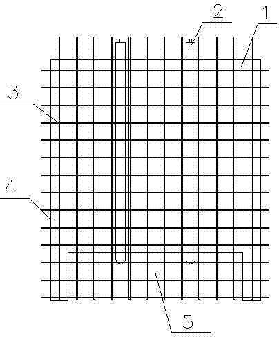
[0024] see figure 2 , the width of the wall body 1 of the concrete prefabricated shear wall is 2400mm, the outriggers are removed, and the cast-in-place section width L=2000mm is reserved for the overlapping parts of the steel bars at the bottom, and the middle part of the wall reinforcement cage 3 is placed by placing two The rubber mandrel 2 reserves two vertical pouring holes corresponding to the cast-in-place section 5 and passing through from top to bottom.

Embodiment 3

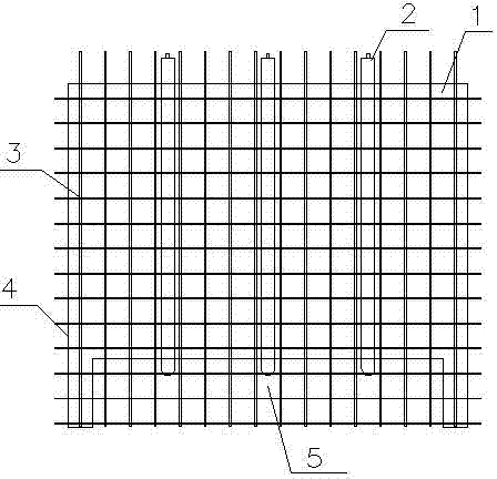
[0026] see image 3 , the width of the wall body 1 of the prefabricated concrete shear wall is 3200mm, the outriggers are removed, and the cast-in-place section width L=2800mm is reserved for the overlapping parts of the steel bars at the bottom, and the middle part of the wall reinforcement cage 3 is placed at intervals. The rubber mandrel 2 reserves three vertical pouring holes corresponding to the cast-in-place section 5 and passing through from top to bottom.

[0027] The concrete prefabricated body of wall described in embodiment 1-3 is poured and molded according to the following steps:

[0028] (1) Molding: Bind the wall reinforcement cage 3 in the prefabricated wall mold 4, and prefabricate the rubber core mold 2 matching the diameter of the vertical pouring hole in the wall body 1 and having a suitable length; The mold 2 penetrates into the wall reinforcement cage 3 that has been bound, and the inflation nozzle is placed outside to avoid sharp hard objects from pierc...


PUM


Abstract

The invention relates to a concrete prefabricated wall body and a vertical pouring hole remaining method thereof. A through vertical pouring hole is formed in the concrete prefabricated wall body corresponding to a cast-in-site section. The vertical pouring hole remaining method comprises producing an inflatable rubber core mold which is matched with the vertical pouring hole in diameter and length, drawing the rubber core mold to penetrate a tied wall body reinforced cage through a rope and enabling an inflatable nozzle to be placed externally; inflating the rubber core mold through an air pump, controlling the monitoring air pressure trough a pressure gauge during inflation and inflating to the specified pressure; fixing the upper side, the lower side, the left side and the right side of the rubber core mold when wall body concrete is poured; performing vibration from the bilateral sides of the rubber core mold simultaneously during concrete vibration to prevent the rubber core mold from moving laterally; deflating the rubber core mold and pulling out the rubber core mold after the concrete is finally set. According to the concrete prefabricated wall body, the design requirements can be met, the total weight of the wall body can be reduced, the wall body vertical pouring hole is reserved in the rubber core mold, the operation is simple, and the labor, the time and materials are saved.

Description

technical field [0001] The invention relates to a concrete prefabricated shear wall, in particular to a concrete prefabricated wall body and a vertical pouring hole placement method thereof. Background technique [0002] At present, when the prefabricated shear wall is installed, when the concrete cast-in-place section at the lap part of the reserved steel bar at the bottom is poured, the air bubbles generated are not easy to release, and the construction speed is slow, the quality is not easy to control, and it is difficult to ensure the fullness of the concrete at the bottom of the wall Shortcomings. Contents of the invention [0003] The present invention aims to solve the above-mentioned problems existing in the installation of existing prefabricated shear walls, and provides a concrete prefabricated wall and a method for placing vertical pouring holes that are convenient for quality control and later pouring. [0004] The technical solution adopted by the present inv...

Claims


Application Information

Patent Timeline
IPC IPC(8): B28B23/02E04B2/56
CPCB28B23/02E04B2/56
Inventor 李哲龙李晓亮索屹楠
Owner CHINA 22MCC GROUP CORP
Why Eureka
Try Eureka