
Forming mould of thermal-insulation layer of thermal-insulation pipeline

A technology for forming molds and thermal insulation layers, which is applied to the field of forming molds for thermal insulation layers of thermal insulation pipes, can solve problems such as damage to thermal insulation layers and uneven surface thickness of thermal insulation layers, and achieve the effects of improving adsorption force and uniform surface thickness.

Inactive Publication Date: 2015-01-07
BEIJING HTN PIPELINE EQUIP
View PDF8 Cites 0 Cited by
  • Summary
  • Abstract
  • Description
  • Claims
  • Application Information

AI Technical Summary

Problems solved by technology

[0008] Therefore, the technical problem to be solved by the present invention is to overcome the technical defects in the prior art that the production mold of the thermal insulation layer of the thermal insulation pipeline cannot be well separated from the thermal insulation layer, resulting in damage to the thermal insulation layer, or easily causing uneven surface thickness of the thermal insulation layer, thereby Propose a molding die for the heat insulation layer of the heat insulation pipe that can be well separated from the heat insulation layer and can ensure the uniformity of the surface thickness of the heat insulation layer

Method used


Image

  • Forming mould of thermal-insulation layer of thermal-insulation pipeline
  • Forming mould of thermal-insulation layer of thermal-insulation pipeline
  • Forming mould of thermal-insulation layer of thermal-insulation pipeline

Examples


Embodiment 1

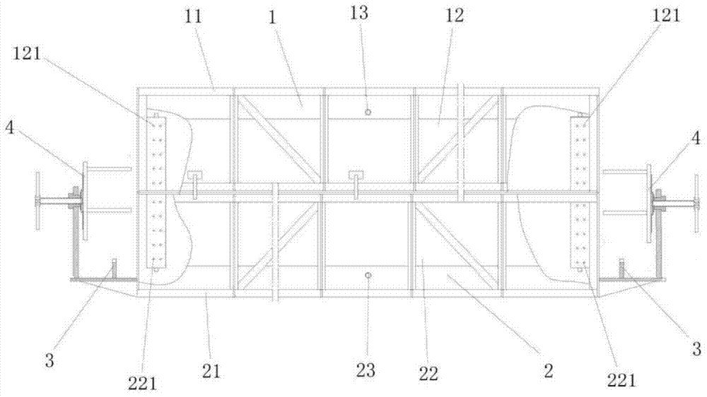
[0046] This embodiment provides a molding die for the insulation layer of the heat-insulating pipeline, such as figure 1 As shown, a mold body is included, and the mold body includes an upper mold 1 and a lower mold 2, and the upper mold 1 and the lower mold 2 form a split mold, and the upper mold 1 and the lower mold 2 respectively have a mold shell 11, 21 and mold liners 12, 22 with semi-cylindrical cavities installed inside corresponding to the mold shells 11, 21; several through holes 121, 221 are formed on the inner walls of the mold liners 12, 22 The outer walls of the mold liners 12, 22 are provided with cavities 122, 222 communicating with the through holes 121, 221, and the mold shells 11, 21 are formed with at least one The through-holes 121, 221 communicate with the air suction ports 13, 23, and the air suction ports 13, 23 are connected with the external vacuum assembly of the mould.

[0047] When using the forming mold of the thermal insulation layer of the heat-...

Embodiment 2

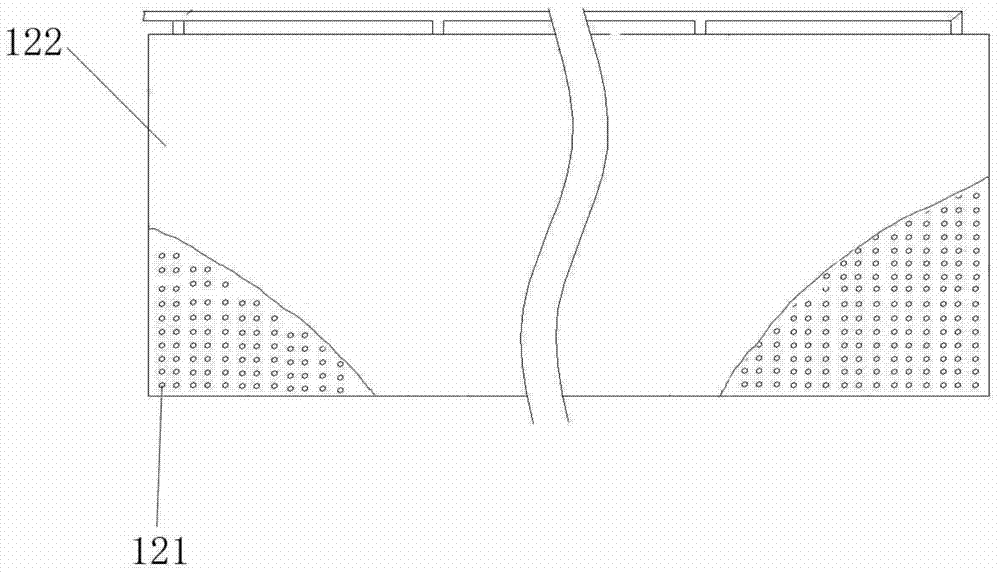
[0058] This embodiment provides a molding die for the heat insulation layer of a heat-insulating pipeline, which is a deformation on the basis of Embodiment 1. In this embodiment, the upper die 1 and the lower die 2 are composed of several sub-mold segments in the axial direction The through holes 121, 221, the air suction ports 13, 23 are arranged on the mold liners 12, 22 of each sub-mould section, and the through holes 14, 24 and The chambers 122 , 222 of the suction ports 13 , 23 .

[0059] By dividing the entire mold into multiple sub-sections, on the one hand, transportation and movement can be facilitated; on the other hand, by increasing or reducing the number of sub-sections, the heat-insulating pipe forming die of the present invention can manufacture heat-insulating pipes with different length requirements. In order not to affect the air pumping work of the vacuum pumping assembly, the through holes 121, 221, the air pumping ports 13, 23 are arranged on the mold lin...

Embodiment 3

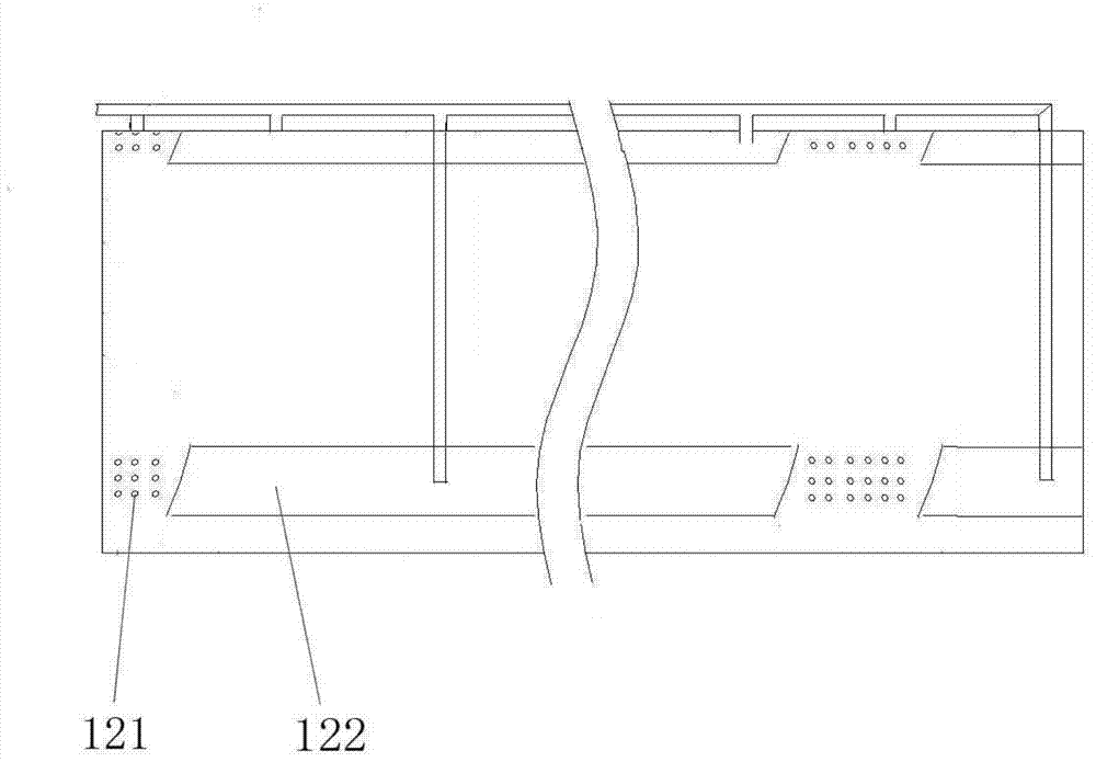
[0064] This embodiment provides a molding die for the heat insulation layer of a heat-insulating pipeline, which is a deformation based on Embodiment 2. In this embodiment, the mold liners 12 and 22 of each sub-die section There are several through-hole forming parts equidistantly arranged along the circumferential direction, and the through-holes 121, 221 are evenly distributed on each of the through-hole forming parts along the axial direction.

[0065] The through-holes 121, 221 are arranged in the form of through-hole 121, 221 forming parts along the circumferential direction, the through-holes 121, 221 are collectively arranged in the through-hole forming parts, and the through-hole forming parts are equidistantly arranged along the circumferential direction, and the upper The structure of the mold liner 121, 221 of the mold 1 and the lower mold 2 is exactly the same, here is the mold liner 121 of the upper mold 1 as an example, as Figure 4 As shown, thereby can ensure t...


PUM


Abstract

The invention relates to a forming mould of a thermal-insulation layer of a thermal-insulation pipeline. The forming mould comprises a mould body, wherein the mould body comprises an upper mould and a lower mould, the upper mould and the lower mould form a bi-parting mould, and are respectively provided with a mould housing and a mould liner which corresponds to the mould housing and internally provided with a semicircular cavity; by forming a plurality of through holes in the inner wall of the mould liners, a cavity communicated with the through holes is arranged on the outer wall of each mould liner, at least one extraction opening communicated with the through holes by virtue of the corresponding cavity is formed in each mould housing, and the extraction openings are connected with a mould external vacuumizing assembly. By arranging the through holes, the cavities and the extraction openings, the vacuumizing assembly is started to ensure that negative pressure is formed in each cavity, and thus a film can be firmly adsorbed on the inner walls of the mould liners, the inner walls of the mould liners can be well separated from a thermal-insulation layer without damaging the thermal-insulation layer, and the surface thickness of the thermal-insulation is relatively uniform.

Description

technical field [0001] The invention relates to a molding die for a heat insulating layer of a heat insulating pipeline, which belongs to the technical field of moulds. Background technique [0002] In the fields of central heating, cooling, oil and gas, etc., the medium conveying pipeline generally adopts a heat-insulated pipeline, and its structure includes a medium conveying pipe, an outer shell and an insulating layer between the medium conveying pipe and the outer shell. Among them, the medium conveying pipe and the outer casing are generally made of polymer or metal, and the heat insulating layer is generally made of a single-layer polyurethane material. Composite thermal insulation layer formed by compounding multiple single layers. [0003] The performance of the heat insulation layer is a key factor affecting the heat insulation performance of the heat insulation pipeline. In the prior art, the heat insulation layer is generally formed in the form of mold foaming. ...

Claims


Application Information

Patent Timeline
IPC IPC(8): B29C44/58
Inventor 周抗冰蔡能韩成鹏
Owner BEIJING HTN PIPELINE EQUIP
Learn More