A transmission structure between adjacent conveying rollers

A transmission structure and conveying roller technology, applied in the field of machinery, can solve problems such as jamming and affecting the conveying system, and achieve the effects of improving stability, avoiding jamming, and improving convenience.

Inactive Publication Date: 2016-04-27
遵化市堡子店兴利铁选厂
View PDF5 Cites 0 Cited by
  • Summary
  • Abstract
  • Description
  • Claims
  • Application Information

AI Technical Summary

Problems solved by technology

[0002] In the prior art, the form of chain transmission is often used between adjacent conveying rollers. However, when the chain transmission form encounters debris, it often gets stuck, thus affecting the entire conveying system.

Method used


Image

  • A transmission structure between adjacent conveying rollers
  • A transmission structure between adjacent conveying rollers
  • A transmission structure between adjacent conveying rollers

Examples


Embodiment Construction

[0017] The present invention will be described in further detail below in conjunction with the accompanying drawings.

[0018] This specific embodiment is only an explanation of the present invention, and it is not a limitation of the present invention. Those skilled in the art can make modifications to this embodiment without creative contribution as required after reading this specification, but as long as they are within the rights of the present invention All claims are protected by patent law.

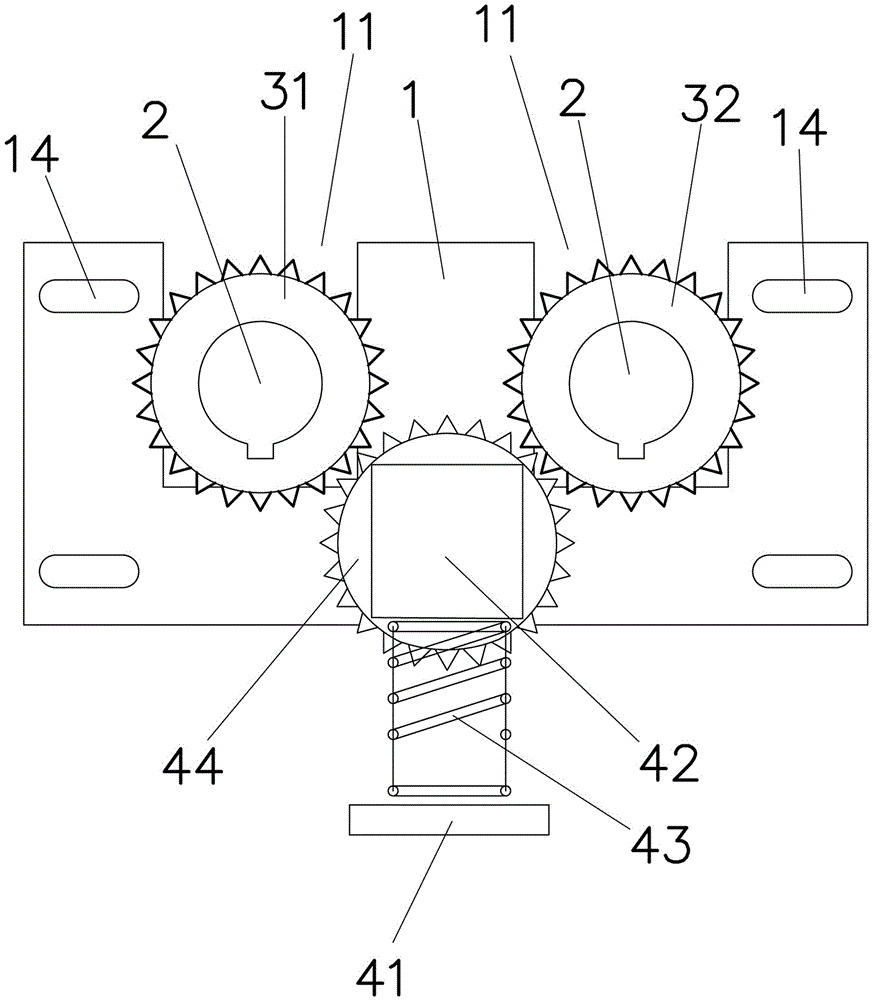
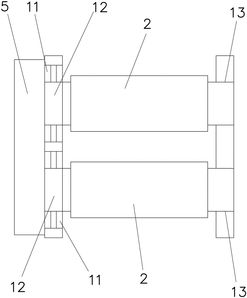
[0019] Example: such as Figure 1-4 As shown, a transmission structure between adjacent conveying rollers includes a frame 1, two conveying rollers 2 rotatably connected to the frame 1, and the ends on the same side of the two conveying rollers 2 are respectively fixedly connected with first gears 31 and the second gear 32.

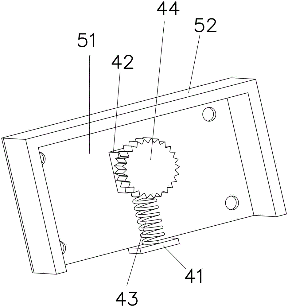
[0020] This embodiment also includes a case 5 fixedly connected to the frame 1 by screws and covered outside the first gear 31 and the second gear 32, and ...


PUM


Abstract

The invention relates to the field of machinery, particularly to an adjacent conveying roller transmission structure. According to the technical scheme, the adjacent conveying roller transmission structure is composed of a frame, two conveying rollers, a first gear, a second gear, a housing and a floating transmission structure, wherein the first gear and the second gear are fixedly connected to the corresponding conveying rollers, the housing is fixedly connected to the frame, and the floating transmission structure is fixedly arranged on the housing. The housing comprises a mounting plate connected to the frame through screws and an abutting plate, which is fixedly connected to the upper portion of one surface of the mounting plate and abuts against the frame on both sides; the floating transmission structure comprises a fixing seat fixedly connected to the low portion of the mounting plate, a floating seat arranged above the fixing seat, springs arranged between the fixing seat and the floating seat, and a third gear which is rotatably connected to the floating seat and engaged with the first gear and the second gear. The adjacent conveying roller transmission structure can effectively avoid jamming of the conveying roller and accordingly improve the stability of an entire conveying system.

Description

technical field [0001] The invention relates to the mechanical field, in particular to a transmission structure between adjacent conveying rollers. Background technique [0002] In the prior art, a chain transmission is often used between adjacent conveying rollers. However, when the chain transmission encounters debris, it often gets stuck, thereby affecting the entire conveying system. Contents of the invention [0003] The purpose of the present invention is to provide a transmission structure between adjacent conveying rollers, which can effectively avoid the phenomenon that the conveying rollers are stuck, thereby improving the stability of the entire conveying system. [0004] The above-mentioned technical purpose of the present invention is achieved through the following technical solutions: a transmission structure between adjacent conveying rollers, comprising a frame, two conveying rollers rotatably connected to the frame, two conveying rollers A first gear and ...

Claims


Application Information

Patent Timeline
Patent Type & Authority Patents(China)
IPC IPC(8): B65G39/10
CPCB65G39/10
Inventor 蔡德林
Owner 遵化市堡子店兴利铁选厂
Why Eureka
Try Eureka