
Drill pipe monitoring method and drill pipe monitoring device

A monitoring device and drill pipe technology, which is applied to the automatic control system of drilling, drilling equipment, earthwork drilling and production, etc. It can solve the problems of large judgment error with rod, false image with rod, and inability to determine the drill pipe, etc., so as to eliminate the problem of with rod Illusion, small judgment error, and the effect of facilitating remedial measures

Active Publication Date: 2017-09-08
BEIJING SANY HEAVY MASCH CO LTD
View PDF5 Cites 0 Cited by
  • Summary
  • Abstract
  • Description
  • Claims
  • Application Information

AI Technical Summary

Problems solved by technology

The defect of this method is that it is impossible to determine the drill pipe with the rod, so it is impossible to determine the corresponding countermeasures after the occurrence of the rod, which makes the countermeasures after the occurrence of the rod unreasonable and cannot effectively avoid the occurrence of the drill pipe with the rod. mechanical damage
In addition, the influence of other external forces in the process of lifting the drill will also affect the change in the pulling force of the main winch, which will cause the false appearance of the rod, so the judgment error of the rod is large

Method used


Image

  • Drill pipe monitoring method and drill pipe monitoring device
  • Drill pipe monitoring method and drill pipe monitoring device
  • Drill pipe monitoring method and drill pipe monitoring device

Examples


Embodiment Construction

[0050] It should be noted that, in the case of no conflict, the embodiments of the present invention and the features in the embodiments can be combined with each other. Various preferred embodiments of the present invention will be further described below in conjunction with the accompanying drawings.

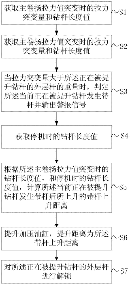
[0051] See figure 1 , Embodiment 1 of the present invention provides a drill pipe monitoring method, comprising the steps of:

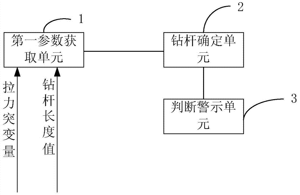
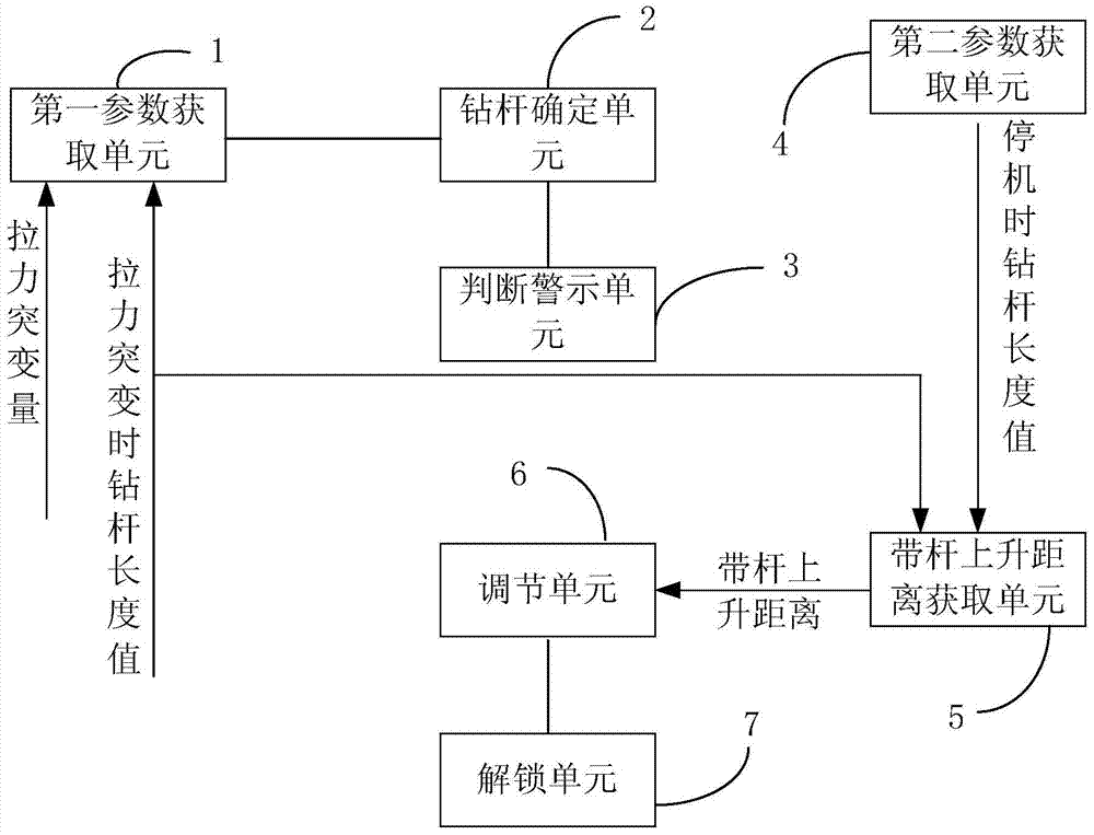
[0052] S1. Obtain the sudden change in pulling force and the length of the drill pipe when the pulling force of the main winch changes suddenly;

[0053] S2. Determine the drill pipe currently being lifted according to the drill pipe length value;

[0054] S3. When the sudden change in tension is greater than or equal to the weight of the outer layer of the drill pipe being lifted, it is determined that the drill pipe currently being lifted has a rod and an alarm signal is output.

[0055] It should be noted that the above-mentioned outer layer rod...


PUM


Abstract

The invention discloses a drill rod monitoring method and a drill rod monitoring device. The drill rod monitoring method comprises the following steps: (S1) the tension break variable and the drill rod length value in the break of a main windlass tension value are obtained; (S2) drill rods being lifted at present are determined according to the drill rod length value; and (S3) when the tension break variable is greater than or equal to the weight of outer-layer rods of the drill rods being lifted, the drill rods being lifted at present generate the rod carrying, and warning signals are output. The drill rod monitoring method, provided by the invention, can judge out a rod carrying area so as to bring convenience for operators to adopt remedial actions, and is low in judgment error.

Description

technical field [0001] The invention relates to the field of rotary drilling rigs, in particular to a drill pipe monitoring method and a drill pipe monitoring device. Background technique [0002] Rotary drilling rig is a construction machine for taking soil and forming holes for cast-in-place piles. Its action principle is mainly to drive the drill rod by the power head to realize the rotation of the rotary bucket to cut the rock and soil, and then lift it to the outside of the hole to unload the soil. After periodic cycle operation, until a hole is formed. Rotary drilling rigs have the advantages of stable power transmission and high efficiency, and are widely used in foundation construction such as cast-in-situ piles, continuous walls, and foundation reinforcement. [0003] The drill rod is one of the important mechanisms for the rotary drilling rig to realize deep hole drilling. The drill rod is set between the power head and the drill bit of the rotary drilling rig to...

Claims


Application Information

Patent Timeline
Patent Type & Authority Patents(China)
IPC IPC(8): E21B44/00
CPCE21B44/00
Inventor 余建明周伟
Owner BEIJING SANY HEAVY MASCH CO LTD
Learn More