Flat tire braking system

A brake system and tire blowout technology, which is applied in the field of automobile safety driving system, can solve problems such as tire blowout detection lag, potential safety hazards, and rear-end collision accidents, so as to avoid rear-end collision accidents, facilitate remedial measures, and ensure driving safety.

Active Publication Date: 2012-09-05
日照新睿招商发展有限公司
View PDF7 Cites 0 Cited by
  • Summary
  • Abstract
  • Description
  • Claims
  • Application Information

AI Technical Summary

Problems solved by technology

[0003] The invention mainly solves the technical problem that the actuator in the original automobile braking system uses a servo device, the structure is complex, and the cost is high; it provides a tire burst braking system with a simple structure, low cost, and more perfect performance
[0004] The invention simultaneously solves the technical problems that the original car cannot automatically start the warning device when braking with a punctured tire, cannot promptly warn the rear vehicles, easily causes rear-end collision accidents, and has potential safety hazards; it provides a car that automatically starts immediately when braking with a punctured tire The warning device reminds the vehicles behind to avoid the occurrence of rear-end collision accidents and ensures the safety of the vehicles.
[0005] The invention also solves the technical problems that the original tire blowout brake system only detects the lack of air, does not detect air leakage, cannot issue warnings as soon as possible, and the tire blowout detection lags behind and is not perfect; it provides a device that can detect air leakage and give an alarm, which is convenient The driver takes remedial measures early to reduce fuel consumption, reduce the occurrence of tire blowouts, and a more perfect tire blowout braking system

Method used


Image

  • Flat tire braking system
  • Flat tire braking system
  • Flat tire braking system

Examples


Embodiment 1

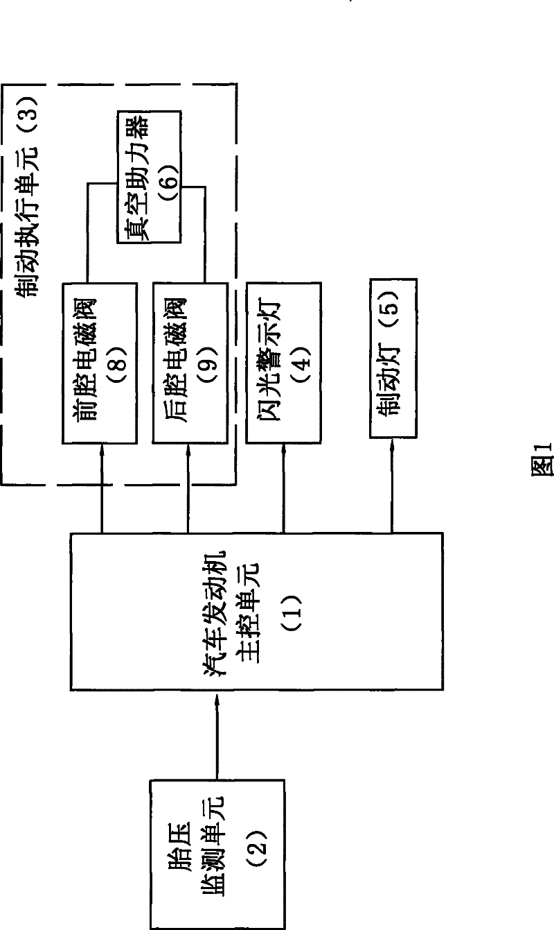
[0026] Embodiment 1: the tire burst brake system of the present embodiment, as figure 1 As shown, it includes an automobile engine main control unit 1 and a tire pressure monitoring unit 2 connected thereto, and a brake execution unit 3. The output of the tire pressure monitoring unit is connected to the input of the automobile engine main control unit, and the output of the automobile engine main control unit is connected to The input of the brake execution unit, the main control unit 1 of the automobile engine also has two outputs, one of which is connected to the driving end of the flashing warning light 4, and the other output is connected to the driving end of the brake light 5.

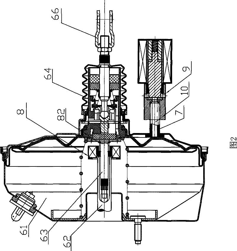
[0027] The brake execution unit 3 is a vacuum booster 6 connected with a front chamber solenoid valve 8 and a rear chamber solenoid valve 9 . like figure 2 As shown, on the one hand, the front chamber solenoid valve 8 and the rear chamber solenoid valve 9 are electrically connected to the outp...


PUM


Abstract

The invention relates to a flat tire braking system which comprises a tire pressure monitoring unit, an automobile engine main control unit and a braking execution unit connected in sequence, wherein the braking execution unit is a vacuum power booster provided with a front cavity solenoid valve and a rear cavity solenoid valve which are connected with the automobile engine main control unit; thefront cavity solenoid valve is connected with a tappet on a braking master cylinder piston, the rear cavity solenoid valve is connected with a mounting bolt on a rear cavity shell, and a push rod of the vacuum power booster is connected with a braking pedal; and the automobile engine main control unit is also provided with two output ends respectively connected with the drive ends of a flash caution light and a braking light. The invention detects blowout by improving a program, controls the front cavity solenoid valve and the rear cavity solenoid valve of the vacuum power booster to brake bythe automobile engine main control unit, has more perfect braking effect, increases the security level of an automobile by a rank, brakes a flat tire in 500 ms, automatically turns the caution light and the braking light on and enables a driver of a rear vehicle to see a caution visual signal of a front vehicle as soon as possible so as to prevent the vehicle from rear collision.

Description

technical field [0001] The invention relates to a vehicle safety driving system, in particular to a tire burst braking system. Background technique [0002] When a car is running at high speed, if a tire suddenly blows out, the braking system of the existing car (such as the BMBS system of our company) will brake the vehicle almost instantly, so that the vehicle can stop smoothly. However, the actuator used in the original automobile braking system is a servo device, which has a complex structure and high cost. Moreover, the control system only considers how to make the vehicle with a puncture stop safely, without a puncture warning device. It usually takes 1 to 2 seconds for the driver to notice the tire blowout from a tire failure. At this time, the driver needs to hold the steering wheel tightly and cannot press the brake warning light button. It is too late to react, prone to rear-end collision accidents. In addition, the original tire blowout braking system generally ...

Claims


Application Information

Patent Timeline
Patent Type & Authority Patents(China)
IPC IPC(8): B60T7/12B60T13/68B60Q1/44
Inventor 李书福杨健赵福全周一平戴关林曾鹏姚明
Owner 日照新睿招商发展有限公司
Why Eureka
Try Eureka