Active oil and gas separator

An active technology of oil and gas separator, applied in the direction of engine components, machines/engines, mechanical equipment, etc., can solve problems such as the decline of the performance and reliability of the whole machine, the inability to meet the closed crankcase ventilation system, and the low efficiency of oil and gas separation. , to achieve the effect of easy machine layout, simple structure and high reliability

Inactive Publication Date: 2017-01-11
CHINA FIRST AUTOMOBILE
View PDF6 Cites 12 Cited by
  • Summary
  • Abstract
  • Description
  • Claims
  • Application Information

AI Technical Summary

Problems solved by technology

[0003] The purpose of the present invention is to provide an active oil-gas separator, which can solve the problem that the performance and reliability of the medium and heavy-duty diesel engines are reduced after the closed crankcase ventilation system is adopted.
[0005] The positive effect of the present invention is that it solves the problem that the oil-gas separation product in the market is low in oil-gas separation efficiency and cannot satisfy the closed crankcase ventilation system; the structure is simple, and it is convenient for the whole machine to be arranged; no maintenance is required for life, and the user's use cost is reduced; reliability High, suitable for medium and heavy-duty diesel engines that are required to meet Euro VI emission regulations

Method used


Image

  • Active oil and gas separator
  • Active oil and gas separator

Examples


Embodiment

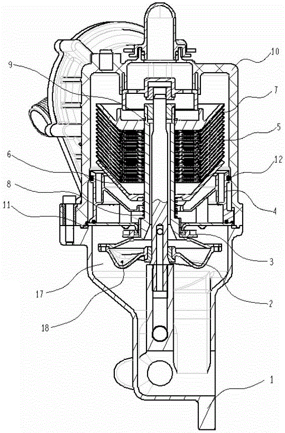
[0010] The high-pressure lubricating oil enters the drive shaft assembly 2 through the base assembly 1, and is sprayed out through two oil injection holes 18 with a diameter of 1.8 mm on the drive shaft assembly 2 and which are symmetrical along the rotation center. The force couple formed by engine oil injection drives the drive shaft to rotate around the center; the laminations 5, the lamination upper body 7 and the lamination lower body 6 are fixed on the drive shaft assembly 2 through the limit spring 8 and the retaining spring 9, and follow the drive shaft assembly 2. Perform high-speed rotation; at this time, the crankcase exhaust gas entering the oil-gas separator through the upper shell assembly 10 passes through the high-speed rotating laminations. The centrifugal force generated by the rotation will cause the liquid oil droplets and particles in the exhaust gas of the crankcase to fly away from the laminations and hit the wall of the shell assembly 10, thereby complet...


PUM


Abstract

The invention relates to an active oil-gas separator which is characterized in that the upper end of a base assembly is fixedly connected with an upper shell assembly, a sealing ring is arranged at the joint of the base assembly and the upper shell assembly, an inner cavity of the base assembly is an oil return cavity, a gas outlet cavity assembly is assembled at the lower end of an inner cavity of the upper shell assembly, a driving shaft assembly is vertically arranged in a cavity formed by the base assembly and the upper shell assembly, an auxiliary separating impeller is arranged on the portion of the driving shaft assembly positioned in the base assembly, an engine oil spraying hole is formed below the driving shaft assembly, a lamination lower body, a lamination and a lamination upper body sleeve the portion of the driving shaft assembly positioned in the upper shell assembly from bottom to top, the lamination lower body is limited by a limiting spring, the lamination upper body is limited by a clamping spring, a pressing plate is arranged in a side cover above the upper shell assembly, a diaphragm is arranged at the pressing plate, the maximum gap is kept between the diaphragm and a gas outlet, and the diaphragm is supported by a pressure adjusting valve spring. The active oil-gas separator can solve the problems that the overall engine performance and reliability of medium-duty and heavy duty diesel engines are reduced after a closed crankcase ventilation system is used.

Description

technical field [0001] The invention relates to an active oil-gas separator, which belongs to the oil-gas separation technology of the crankcase ventilation system of a diesel engine and belongs to the technical field of automobiles. Background technique [0002] The crankcase ventilation system is an important part of the engine. With the increasingly stringent emission regulations, the crankcase ventilation system has gradually become the content of the regulations. For example, GB11340 issued in 2005 clearly requires that gasoline engines must adopt a closed crankcase ventilation system. Although there is no mandatory requirement for diesel engines at present, the latest Euro VI emission regulations clearly point out that the exhaust gas discharged from the crankcase ventilation system is directly introduced into the exhaust gas for unified testing. The implementation of this regulation will undoubtedly have a huge impetus to the technologies related to the crankcase ven...

Claims


Application Information

Patent Timeline
Patent Type & Authority Patents(China)
IPC IPC(8): F01M13/04
CPCF01M13/0416F01M2013/0016F01M2013/0422
Inventor 柳国立韩俊楠王睿智戈非葛海龙李文祥刘正勇张蒙吴贵荣张国宇
Owner CHINA FIRST AUTOMOBILE
Why Eureka
Try Eureka