Water mixing valve of water heater
A technology for mixing water valves and water heaters, which is applied in the direction of multi-way valves, valve devices, engine components, etc. It can solve the problems of hot and cold mixed water temperature, difficulty in mixing water temperature, and no good solution, etc., to achieve convenient adjustment , the effect of improving comfort
- Summary
- Abstract
- Description
- Claims
- Application Information
AI Technical Summary
Problems solved by technology
Method used
Image

Examples
Embodiment Construction
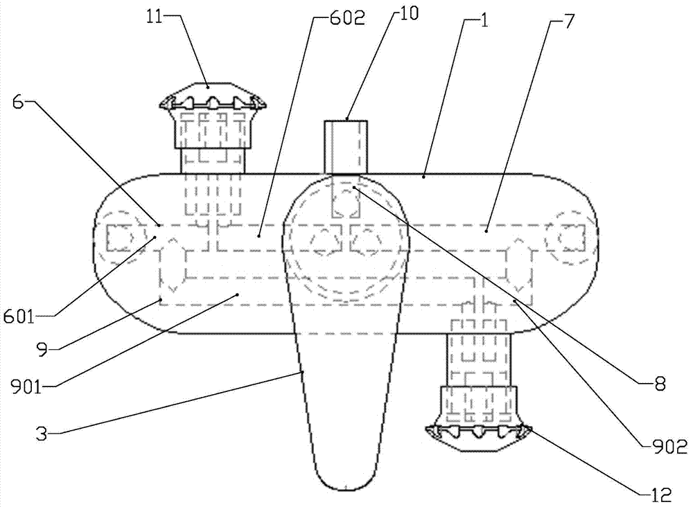
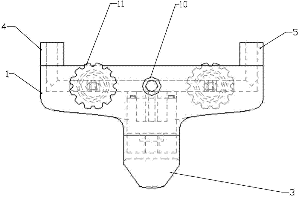
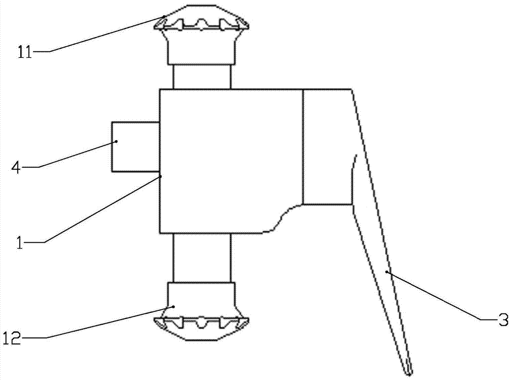
[0039] Refer to the attached figure 1 to attach Figure 10 A water heater mixing valve of the present invention will be described in detail below.
[0040] A water heater mixing valve of the present invention, its structure includes a valve body 1, a water mixing regulating valve core 2 and a water mixing regulating valve handle 3, the water mixing regulating valve core 2 is arranged on the front side of the valve body 1, and Connected with the mixing water regulating valve handle 3, the left and right ends of the rear side of the valve body 1 are respectively provided with a cold water inlet 4 and a hot water inlet 5, and the valve body 1 is respectively provided with a cold water outlet pipe 6, Hot water outlet pipeline 7, mixed water outlet pipeline 8 and cold water inlet pipeline 9;
[0041] The cold water outlet pipe 6 and the hot water outlet pipe 7 are arranged on the left side and the right side of the valve body 1 respectively, the right side of the cold water outle...
PUM
 Abstract
Description
Claims
Application Information
 - Generate Ideas
- Intellectual Property
- Life Sciences
- Materials
- Tech Scout
- Unparalleled Data Quality
- Higher Quality Content
- 60% Fewer Hallucinations
Browse by: Latest US Patents, China's latest patents, Technical Efficacy Thesaurus, Application Domain, Technology Topic, Popular Technical Reports.
© 2025 PatSnap. All rights reserved.Legal|Privacy policy|Modern Slavery Act Transparency Statement|Sitemap|About US| Contact US: help@patsnap.com