
Temperature adjustment system for energy storage device room using waste heat from energy storage inverter

A technology of energy storage inverter and energy storage device, which is applied in the field of temperature regulation system and all-vanadium liquid flow energy storage power station, can solve problems such as energy waste, and achieve the effect of reducing operating cost and reducing heating load.

Active Publication Date: 2017-02-15
中国能源建设集团辽宁电力勘测设计院有限公司
View PDF6 Cites 0 Cited by
  • Summary
  • Abstract
  • Description
  • Claims
  • Application Information

AI Technical Summary

Problems solved by technology

From this we found that, on the one hand, the heat of the inverter needs to be dissipated to the outside through ventilation; One row and one heating causes energy waste, so the present invention takes this as a focus to solve the problem of actual waste energy reuse

Method used


Image

  • Temperature adjustment system for energy storage device room using waste heat from energy storage inverter
  • Temperature adjustment system for energy storage device room using waste heat from energy storage inverter
  • Temperature adjustment system for energy storage device room using waste heat from energy storage inverter

Examples


Embodiment Construction

[0020] See figure 1 — Figure 7 , the specific implementation is as follows:

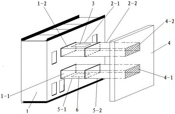
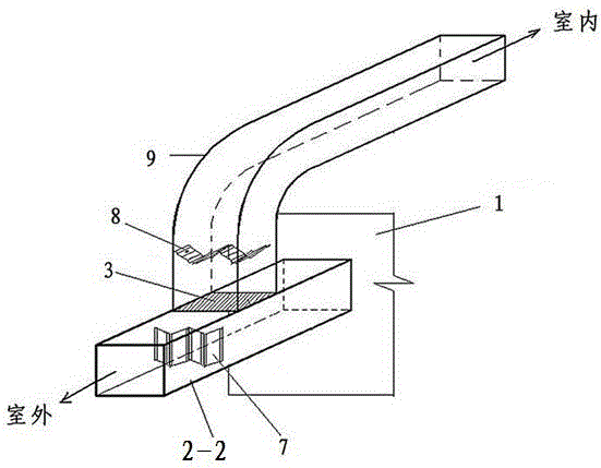
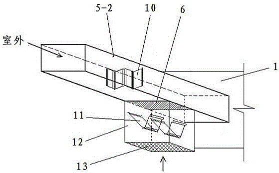
[0021] The inverter 1 is provided with an air inlet 1-1 and an air outlet 1-2, and the outdoor wall 4 of the energy storage device is provided with an air inlet 4-1 and an air outlet 4-2, and the air inlet 1-1 of the inverter The air inlet pipe is connected with the air inlet 4-1 on the outer wall of the energy storage room, and the air inlet pipe is composed of a non-detachable air inlet pipe 5-2 and a detachable air inlet pipe 5-1 with a connecting flange , the air inlet external interface 6 is set under the detachable air inlet pipe 5-1; the exhaust pipe is connected between the air outlet 1-2 of the inverter and the air outlet 4-2 on the outer wall of the energy storage room, and the air outlet The air duct is composed of a section of non-detachable exhaust duct 2-2 and a section of detachable exhaust duct 2-1 with a connecting flange, and the indoor air exhaust external interface 3 is arrange...


PUM


Abstract

Disclosed is an energy storage inverter waste heat utilized temperature regulation system of an energy storage device chamber. The energy storage inverter waste heat utilized temperature regulation system is characterized in that an air inlet pipe and an air exhaust pipe are connected between an inverter and the outer wall of the energy storage chamber; the air inlet pipe is connected with an air inlet pipe drainage duct; an electric split multi-blade regulating valve is arranged in the air inlet pipe drainage duct; the air inlet pipe which is connected with the outer wall of the energy storage chamber and cannot be detached is provided with an electric split multi-blade regulating valve; the air exhaust pipe is connected with an air exhaust pipe drainage duct; the air exhaust pipe drainage duct is provided with an electric split multi-blade regulating valve which is used for controlling the air exhaust; the air exhaust pipe which is connected with the outer wall of the energy storage chamber and cannot be detached is provided with an electric split multi-blade regulating valve; a plurality of temperature sensors and electric heaters are arranged at different positions in the energy storage chamber respectively; a starting switch of every electric heater is connected with a temperature control processor; a motor of every electric split multi-blade regulating valve is connected with the temperature control processor through the corresponding starting switch. According to the energy storage inverter waste heat utilized temperature regulation system of the energy storage device chamber, the temperature regulation of the energy storage device chamber is performed through the waste heat of the energy storage inverter and accordingly the waste energy is rationally utilized and the running cost is reduced.

Description

technical field [0001] The invention belongs to a supporting facility for electric power equipment, in particular to a temperature adjustment system for an energy storage device room using waste heat from an energy storage inverter, which is suitable for an all-vanadium liquid flow energy storage power station. Background technique [0002] In recent years, new energy industries such as wind power and photovoltaics have developed rapidly. Objectively speaking, this kind of development requires the rapid promotion of the necessary support for the large-capacity energy storage industry. Energy storage technology can solve the randomness and volatility of new energy power generation to a large extent, and allow large-scale wind power and photovoltaic power generation to be easily and reliably integrated into the conventional power grid. Energy storage technology is also of great significance to peak regulation and frequency regulation, energy conservation and environmental pro...

Claims


Application Information

Patent Timeline
Patent Type & Authority Patents(China)
IPC IPC(8): F24D12/02F24D19/08F24D19/10H05K7/20
CPCY02B30/00
Inventor 李平平刘麾张志强王宏陈亮孟丽君范卫国李旭胡湜
Owner 中国能源建设集团辽宁电力勘测设计院有限公司
Learn More