Anti-tensile optical fiber contact and optical fiber connector provided with same

A technology for optical fiber connectors and optical fiber contacts, which is applied in the coupling of optical components, optical waveguides, light guides, etc., can solve the problems of locking parts that are easy to fall off, and achieve the effects of reliable connection, convenient use, and loss prevention

Inactive Publication Date: 2015-01-07
CHINA AVIATION OPTICAL-ELECTRICAL TECH CO LTD
View PDF4 Cites 0 Cited by
  • Summary
  • Abstract
  • Description
  • Claims
  • Application Information

AI Technical Summary

Problems solved by technology

[0004] The purpose of the present invention is to provide an anti-pull optical fiber contact to solve the problem that the locking part of the existing MT optical fiber contact is easy to fall off

Method used


Image

  • Anti-tensile optical fiber contact and optical fiber connector provided with same
  • Anti-tensile optical fiber contact and optical fiber connector provided with same
  • Anti-tensile optical fiber contact and optical fiber connector provided with same

Examples


Embodiment Construction

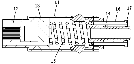
[0024] Examples of pull-out resistant fiber optic contacts, such as Figure 1-6 As shown, the anti-pulling optical fiber contact includes a housing 11 , an MT ferrule 12 , a positioning seat 13 and a locking mechanism, wherein the locking mechanism includes a locking member 14 , a spring 15 and a push rod component.

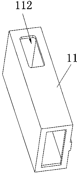
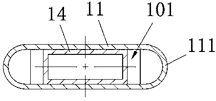
[0025] The casing 11 is a rectangular casing. In this embodiment, the front end of the casing 11 is provided with an inturned edge, and the outer peripheral surface of the MT pin 12 is provided with an inturned edge facing forward to stop the front end of the casing 11. Compatible step surfaces. The MT pin 12, the positioning seat 13, the spring 15 and the locking piece 14 are sequentially loaded into the housing 11 from the rear end of the housing 11, and the ejector part is inserted on the locking piece 14, wherein the locking piece 14 is connected with the locking piece 14. The housings 11 are fixedly assembled together. In this embodiment, both the housing ...


PUM


Abstract

The invention relates to the field of optical fiber connectors, in particular to an anti-tensile optical fiber contact and an optical fiber connector provided with the anti-tensile optical fiber contact. The anti-tensile optical fiber contact comprises a shell. An MT contact pin and a locating seat are sequentially assembled in the shell from front to back. A locking mechanism is further assembled at the rear end of the shell. The locking mechanism comprises a locking piece fixed to the rear end of the shell. The shell and the locking piece are both metal pieces. The locking piece is provided with an insertion part inserted into the shell. The insertion part is provided with clamping grooves. The parts, corresponding to the clamping grooves, of the shell deform through stamping and are clamped in the corresponding clamping grooves. According to the anti-tensile optical fiber contact, the shell and the locking piece are both the metal parts, the locking piece is provided with the insertion part inserted into the shell, the insertion part is provided with the clamping grooves, and the parts, corresponding to the clamping grooves, of the shell deform through stamping and are clamped in the corresponding clamping grooves, so reliable connection between the shell and the locking piece can be realized; consequently, the problem that the locking piece of an existing MT optical fiber contact is prone to falling off is solved.

Description

technical field [0001] The invention relates to the field of optical fiber connectors, in particular to an anti-pulling optical fiber contact piece and an optical fiber connector using the contact piece. Background technique [0002] At present, the optical fiber connectors using MT contacts are mainly MPO and MTRJ type optical fiber connectors with a single MT contact. Due to the small number of contacts included in this optical fiber connector, it cannot meet the requirements in some occasions and has the problem of inconvenient use. [0003] The detachable MT contact includes MT pins, housings, positioning seats, and claws that extend outwards on the housing. The MT pins are assembled at the front end of the housing, and the positioning seat is located in the housing on the MT socket. At the rear end of the needle, the spring top is mounted on the rear end of the positioning seat. The claw is made of elastic plastic parts and there is no fastening structure with the she...

Claims


Application Information

Patent Timeline
IPC IPC(8): G02B6/38
CPCG02B6/3807
Inventor 郝黎明王瑜郑燕华
Owner CHINA AVIATION OPTICAL-ELECTRICAL TECH CO LTD
Why Eureka
Try Eureka