

LED (light-emitting diode) light mixing device
A light mixing device, LED light source technology, applied in lighting devices, display devices, fixed lighting devices, etc., can solve the problems of increasing the optical film, increasing the cost of the LED backlight module, and reducing the overall brightness of the LED backlight module, etc. Achieve the effect of increasing light penetration and eliminating shadows
Active Publication Date: 2015-01-07
TPV DISPLAY TECH (XIAMEN) CO LTD
View PDF4 Cites 10 Cited by
- Summary
- Abstract
- Description
- Claims
- Application Information
AI Technical Summary
Problems solved by technology
[0006] 1. Increasing the number of optical films increases the cost of LED backlight modules;
[0007] 2. Increase the number of optical films to reduce the overall brightness of the LED backlight module
Method used
View moreImage
Smart ImageViewing Examples

Examples
Embodiment 1
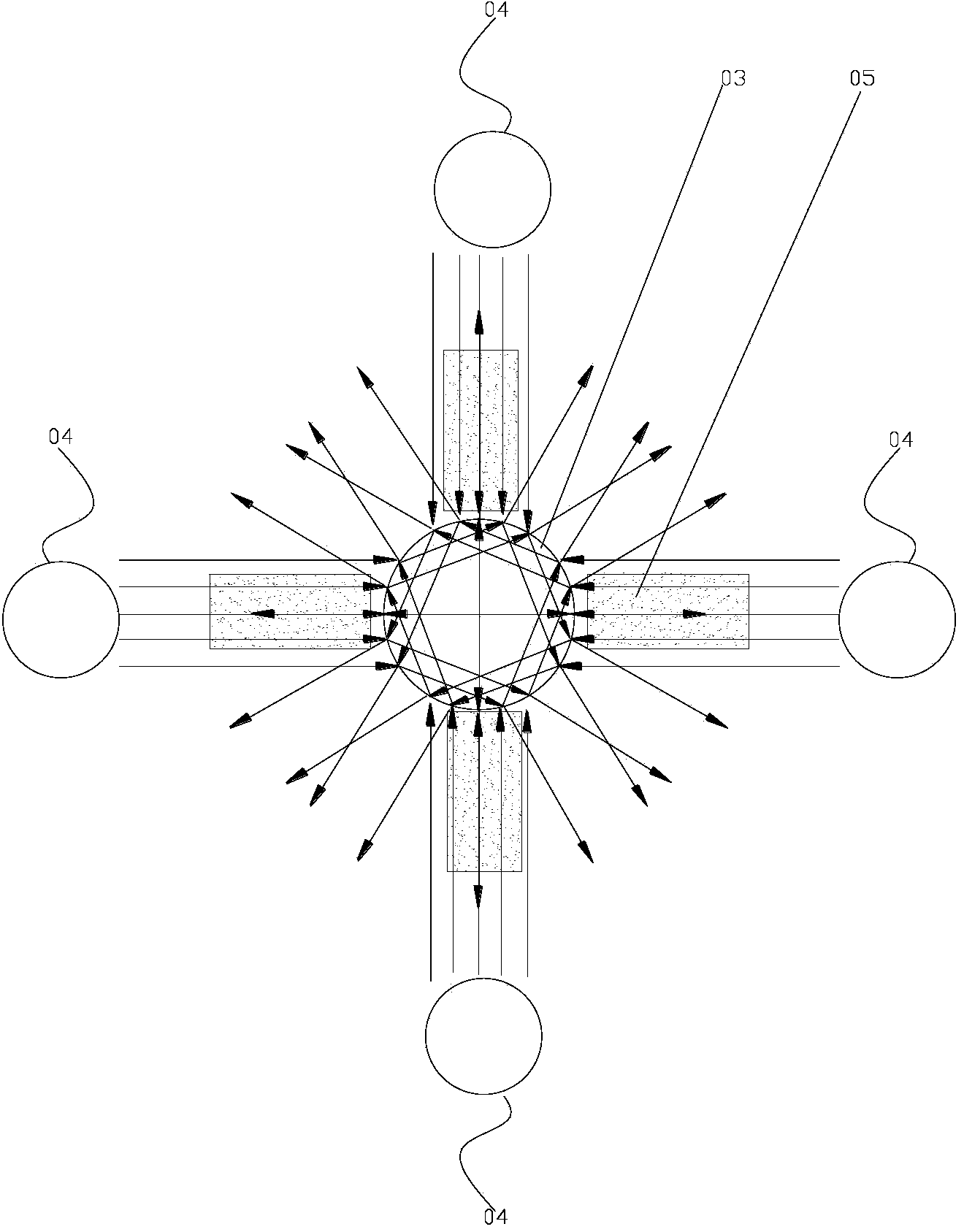
[0037] Such as Figure 4 As shown, the support column 3 is a schematic arrangement position of a quadrangular prism or a prism relative to the LED light source 4 .
Embodiment 2
[0039] Such as Figure 5 As shown, the support column 3 is a hexagonal prism or a truncated prism relative to the schematic arrangement position of the LED light source 4 .
Login to View More PUM
| Property | Measurement | Unit |
|---|---|---|
| transmittivity | aaaaa | aaaaa |
Abstract
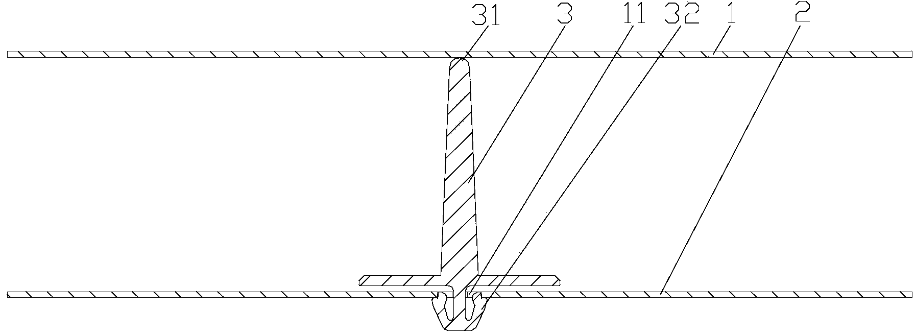
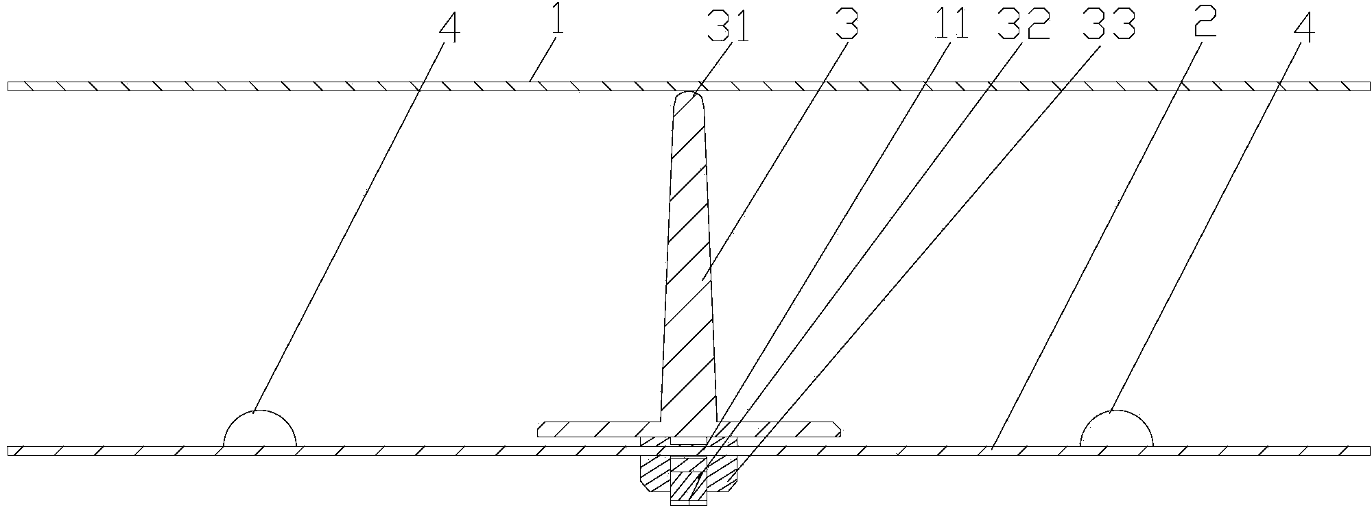
The invention discloses an LED (light-emitting diode) light mixing device which comprises a back panel, an optical film, LED light sources and a supporting column. The optical film is arranged above the back panel, and the LED light sources are arranged on the back panel and distributed to form a central symmetric figure. The supporting column is arranged between the back panel and the optical film and located at the center of the central symmetric figure. The supporting column is provided with a bottom, a top and sides, wherein the bottom is fixed on the back panel, the top supports the optical film, a side surface surrounds the sides, and the LED light sources are located on the perpendicular bisectors of the bottom edges of the sides of the supporting column respectively. The LED light sources of the LED light mixing device form the central symmetric figure, the supporting column of a prism or prismatic table structure is made of transparent materials and located at the center of the central symmetric figure, so that shadows caused by the supporting column in an LED backlight module are removed with low cost.
Description
[0001] This application is a divisional application with the application number "201210257868.0" and the invention title "a support column for LED backlight module" submitted to the State Intellectual Property Office on July 23, 2012. technical field [0002] The invention relates to the technical field of LED light optics, in particular to an LED light mixing device for constructing a light mixing space, which can be applied to the fields of backlight modules of liquid crystal display equipment, lighting fixtures, and advertising light boxes. Background technique [0003] Liquid crystal display technology has always been used in portable electronic products such as notebook computers, mobile phones, digital cameras, camcorders, and PDAs. In addition to these smaller portable products, the manufacturing technology of large-size liquid crystal panels has also matured recently. For example, desktop LCD monitors have replaced CRT monitors, and LCD TVs are also replacing traditi...
Claims
Login to View More Application Information
Patent Timeline
 Patent Type & AuthorityApplications(China)
IPC IPC(8): G02F1/13357F21S8/00G09F13/00F21Y101/02
CPCG02F1/133603G02F1/133608G02F1/133609
Inventor林韡林博瑛郑俊义
OwnerTPV DISPLAY TECH (XIAMEN) CO LTD