Optical fiber phase shift device capable of compensating optical path difference

A technology for compensating light and path difference, applied in the field of interferometry, can solve problems such as complex structure, achieve the effect of simplifying structure, simple structure, and realizing the interferometry process

Active Publication Date: 2018-01-12
SHANGHAI INST OF OPTICS & FINE MECHANICS CHINESE ACAD OF SCI
View PDF7 Cites 0 Cited by
  • Summary
  • Abstract
  • Description
  • Claims
  • Application Information

AI Technical Summary

Problems solved by technology

For example, in the prior art (see G.E.Sommargren, D.W.Phillion, M.A.Johnson, et al, "100-picometer interferometry for EUVL", SPIE Vol.4688, 316-328, 2002), it is realized by devices such as beam splitters, PZTs, and corner cubes Phase shift and optical path compensation function, but the phase shift and optical path compensation are divided into two optical paths, the structure is complex

Method used


Image

  • Optical fiber phase shift device capable of compensating optical path difference
  • Optical fiber phase shift device capable of compensating optical path difference

Examples


Embodiment 1

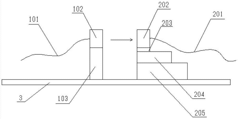
[0016] Embodiment 1: as figure 1 As shown, a fiber optic phase shift device capable of compensating optical path difference includes a first fiber coupler module, a second fiber coupler module and a base 3 . The first optical fiber coupler module is composed of a first optical fiber transmission line 101, a five-degree-of-freedom plus rotation adjustment optical fiber coupler 102, and a first bracket 103. The optical fiber coupler 102 is fixed in position by the first bracket 103, and the first optical fiber transmission line 101 is coupled with an optical fiber. The second optical fiber coupler module is composed of a second optical fiber transmission line 201, a five-degree-of-freedom plus rotation adjustment optical fiber coupler 202, a second bracket 203, a micro-motion translation stage 204, and a macro-motion translation stage 205. The stage 204 is fixed on the macro-motion stage 205 , the fiber coupler 202 is fixed on the micro-motion stage 204 by the second bracket 203...

Embodiment 2

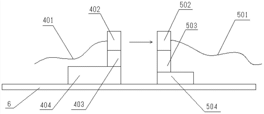
[0020] Embodiment 2: as figure 2 As shown, an optical fiber phase shifting device capable of compensating optical path difference includes a first fiber coupler module, a second fiber coupler module and a base 6 . The first optical fiber coupler module is composed of an optical fiber transmission line 401, a five-degree-of-freedom plus rotation adjustment optical fiber coupler 402, a bracket 403, and a macro-motion translation stage 404. The fiber optic coupler 402 is fixed on the macro-motion translation stage 404 by the bracket 403. It is connected with the fiber coupler 402; the second fiber coupler module is composed of a fiber optic transmission line 501, a five-degree-of-freedom plus rotation adjustment fiber coupler 502, a bracket 503 and a micro-movement stage 504, and the fiber coupler 502 is fixed on the micro-motion stage 504 by the bracket 503. On the moving stage 504 , the optical fiber transmission line 501 is connected with the optical fiber coupler 502 .

[0...


PUM


Abstract

The invention discloses an optical fiber phase shifting device capable of compensating optical path difference. The optical fiber phase shifting device capable of compensating the optical path difference comprises a pedestal, and a first optical fiber coupler module and a second optical fiber coupler module respectively fixed at two ends of the pedestal, wherein the first optical fiber coupler module and the second optical fiber coupler module are aligned to each other, the first optical fiber coupler module comprises a first optical fiber transmission line, a first five-freedom rotating regulating optical fiber coupler and a first bracket, the first five-freedom rotating regulating optical fiber coupler is fixed on the pedestal through the first bracket, and the first optical fiber transmission line is connected with the first five-freedom rotating regulating optical fiber coupler. The optical fiber phase shifting device capable of compensating the optical path difference generates phase shifting outside the optical path of a measured imaging system, eliminates the system error caused by traditional phase shifting, simplifies the overall structure of the measuring system and has advantages of simple structure and easiness in assembling, and the optical fiber phase shifting device is capable of compensating the special optical path difference.

Description

technical field [0001] The invention relates to the field of interferometric measurement, in particular to an optical fiber phase shift device capable of compensating optical path difference that generates phase shift outside the optical path of the measurement imaging system. Background technique [0002] In a variety of experiments and systems based on interferometric optics, it is desirable to control the phase of the beam, including point diffraction interferometer, transverse shear interferometer, phase profilometry and holographic interferometry, stellar interferometry, etc., and the optical phase shift can be different. way to introduce. [0003] The general phase shift methods include piezoelectric ceramic (PZT) phase shift, grating phase shift, polarization phase shift and so on. However, these phase shifting devices can only produce a phase shift of a few wavelengths. In some interferometers using short coherent light sources, not only high-precision phase shift ...

Claims


Application Information

Patent Timeline
Patent Type & Authority Patents(China)
IPC IPC(8): G02F1/225G02B6/26G01B9/02
CPCG01B9/02G02B6/262G02F1/225
Inventor 冯鹏唐锋王向朝
Owner SHANGHAI INST OF OPTICS & FINE MECHANICS CHINESE ACAD OF SCI
Why Eureka
Try Eureka