Interferometer phase shifting device
A technology of interferometer and phase shift, applied in the field of interferometry, can solve problems such as complex structure, achieve the effect of simplifying the system structure, realizing the process of interferometry, and simple structure
- Summary
- Abstract
- Description
- Claims
- Application Information
AI Technical Summary
Problems solved by technology
Method used
Image
Examples
Embodiment 1
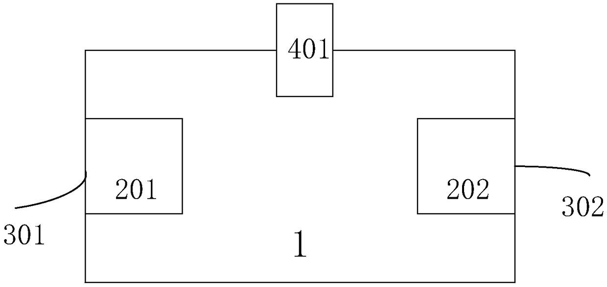
[0031] Embodiment 1: as figure 1 As shown, an interferometer phase shifting device includes a gas-tight container 1 , a first fiber coupler 201 , a second fiber coupler 202 , a first fiber transmission line 301 , a second fiber transmission line ( 302 ) and an air pressure control module 401 .
[0032] The position connection relationship of each component is as follows:
[0033] The first optical fiber coupler 201 is fixed on one side of the airtight container 1, the second optical fiber coupler 202 is fixed on the other side of the gastight container 1, the first optical fiber transmission line 301 is connected on the first optical fiber coupler 201, and the second optical fiber coupler 202 is fixed on the other side of the airtight container 1. The fiber transmission line 302 is connected to the second fiber coupler 202, and the first fiber coupler 201 and the second fiber coupler 202 are aligned with each other. The air pressure control module 401 is fixed on the airtight...
Embodiment 2
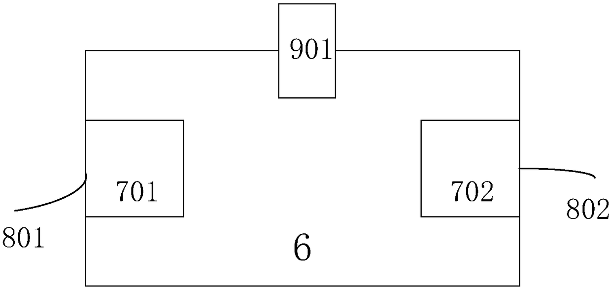
[0037] Embodiment 2: as figure 2 As shown, an interferometer phase shifting device includes a gas-tight container 6 , a first fiber coupler 701 , a second fiber coupler 702 , a first fiber transmission line 801 , a second fiber transmission line ( 802 ) and a temperature control module 901 .
[0038] The position connection relationship of each component is as follows:
[0039] The first optical fiber coupler 701 is fixed on one side of the airtight container 6, the second optical fiber coupler 702 is fixed on the other side of the airtight container 6, the first optical fiber transmission line 801 is connected on the first optical fiber coupler 701, and the second optical fiber coupler 702 is fixed on the other side of the airtight container 6. The fiber transmission line 802 is connected to the second fiber coupler 702, and the first fiber coupler 701 and the second fiber coupler 702 are aligned with each other. The temperature control module 901 is fixed on the airtight c...
PUM
 Abstract
Description
Claims
Application Information
 - R&D
- Intellectual Property
- Life Sciences
- Materials
- Tech Scout
- Unparalleled Data Quality
- Higher Quality Content
- 60% Fewer Hallucinations
Browse by: Latest US Patents, China's latest patents, Technical Efficacy Thesaurus, Application Domain, Technology Topic, Popular Technical Reports.
© 2025 PatSnap. All rights reserved.Legal|Privacy policy|Modern Slavery Act Transparency Statement|Sitemap|About US| Contact US: help@patsnap.com


