Lens module and projection device

A lens module and lens barrel technology, applied in projection devices, optics, instruments, etc., can solve problems such as optical path offset, poor picture, lens optical path offset, etc., to ensure the effect of image quality.

Active Publication Date: 2016-01-27
QISDA OPTRONICS (SUZHOU) CO LTD
View PDF10 Cites 0 Cited by
  • Summary
  • Abstract
  • Description
  • Claims
  • Application Information

AI Technical Summary

Problems solved by technology

[0003] However, because the extended lens of the short-focus projection device is relatively heavy, it is easy to cause the optical path of the lens to shift when subjected to external shocks, resulting in poor pictures, and the optical path shift of the lens is difficult to repair, so a support is needed to support the lens
Traditional supports usually use a whole piece of rubber to contact the lens barrel to play a buffer role. Due to assembly tolerances, excessive support force will also cause the problem of optical path deviation

Method used


Image

  • Lens module and projection device
  • Lens module and projection device
  • Lens module and projection device

Examples


Embodiment Construction

[0036] In order to have a further understanding of the purpose, structure, features, and functions of the present invention, the following detailed descriptions are provided in conjunction with the embodiments.

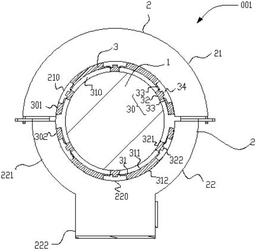
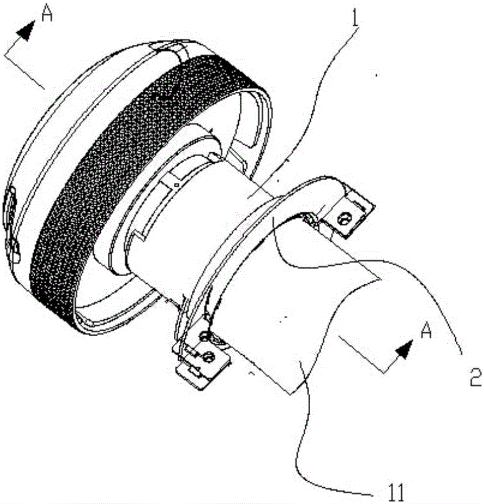
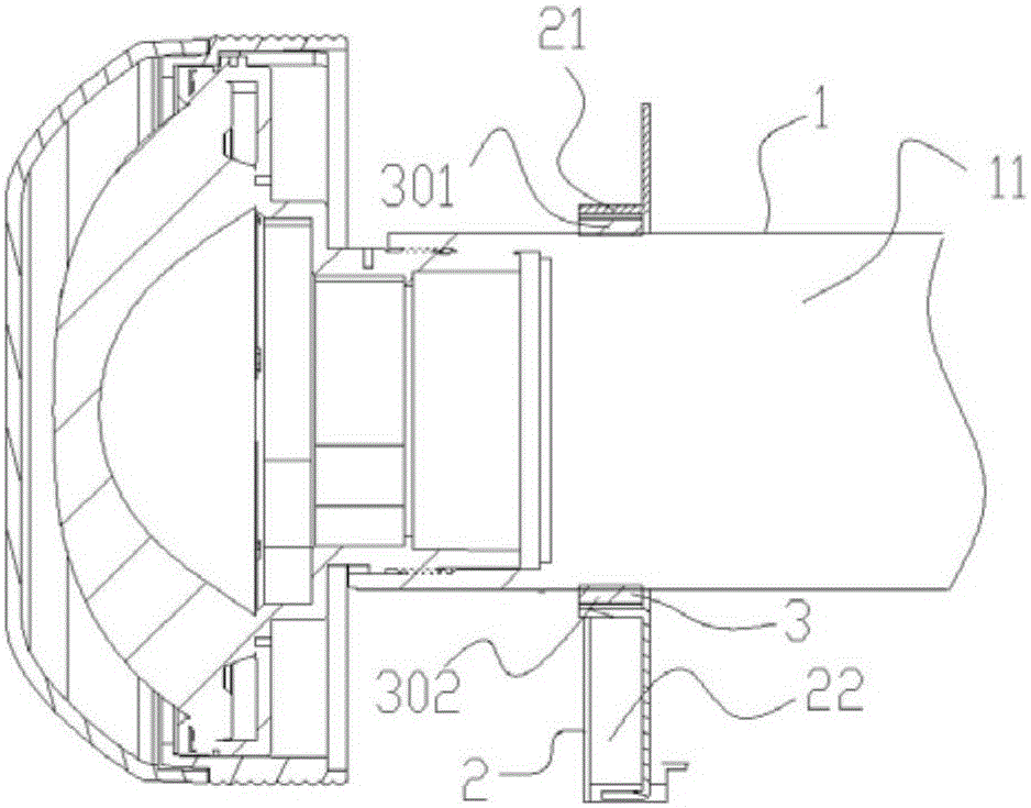
[0037] Reference Figure 1 to Figure 5 As shown, a schematic structural diagram of an embodiment of a lens module of the present invention is disclosed. The lens module 001 includes a lens barrel 1, a support 2 and a buffer 3. Wherein, the supporting member 2 is sleeved on the lens barrel 1 and supports the lens barrel 1. The buffer member 3 is disposed between the lens barrel 1 and the support member 2, and is used to buffer the force of the support member 2 on the lens barrel 1 when the lens module 001 is impacted by an external force, so as to avoid the deviation of the optical path of the lens. Causes the problem of poor picture, and the buffer 3 also overcomes the assembly tolerance, has a weak support for the lens when it is static, and does not generate an excessi...


PUM


Abstract

The invention discloses a lens module and a projection device. The lens module comprises a lens cone, a supporting part and a buffering part, wherein the supporting part is arranged on the lens cone in a sleeving mode and supports the lens cone, the buffering part is arranged between the lens cone and the supporting part, and the buffering part is provided with a main portion and multiple buffering portions. Each buffering portion is provided with a boss and a connecting portion, wherein the boss abuts against the lens cone, the connecting portion is connected with the main portion and the boss, and the connecting portion can deform. Hollow areas are form in the buffering part and correspond to the bosses, a gap is formed between the buffering part and the lens cone, and the gap and the hollow areas are used for providing a space for deformation of the buffering portions so that external impact can be buffered effectively, the situation that poor images are generated due to deviation of the light path of a lens can be avoided, and imaging quality can be guaranteed. Meanwhile, the buffering part abuts against the lens cone and deforms to counteract assembly tolerance, and the situation that the precision of the light path is affected due to deviation of the light path when local stress is too large is avoided.

Description

Technical field [0001] The invention relates to a projection device, in particular to a lens module with a structure to relieve external impact. Background technique [0002] With the rapid development of electronic technology, people's requirements for high-definition projection equipment are becoming increasingly strong. Traditional projection devices with long focal lengths and narrow viewing angles are difficult to meet the requirements in terms of size and projection image quality. The short-focus projection device has the advantage that it can project a picture of about 80-120 inches in a short distance (generally about 1-1.5 meters) and is becoming increasingly important. For example, when the projection space is not large, but a larger screen needs to be displayed, especially in a small meeting room, this short-throw projection device is very suitable. [0003] However, since the extended lens of the short-focus projection device is relatively heavy, when it is subject to...

Claims


Application Information

Patent Timeline
Patent Type & Authority Patents(China)
IPC IPC(8): G03B21/14
CPCG03B21/14
Inventor 谈雪峰郝文光
Owner QISDA OPTRONICS (SUZHOU) CO LTD
Why Eureka
Try Eureka