Bus-system LED display system point-by-point fault detection method and application thereof

A technology for display systems and LED lamps, applied in general control systems, control/adjustment systems, test/monitoring control systems, etc., can solve problems such as lack of color, lack of emergency treatment mechanisms, and flickering

Active Publication Date: 2015-01-07
SHANGHAI GRAND LIGHT
View PDF7 Cites 9 Cited by
  • Summary
  • Abstract
  • Description
  • Claims
  • Application Information

AI Technical Summary

Problems solved by technology

[0002] With the rapid development of LED technology in recent years, more and more LEDs are used in the field of lighting, such as urban landscape lights, but at the same time, some areas or parts of many projects appear to be lack of color, flickering and other phenomena due to faults, which give people visual defec

Method used


Image

  • Bus-system LED display system point-by-point fault detection method and application thereof

Examples


Embodiment 1

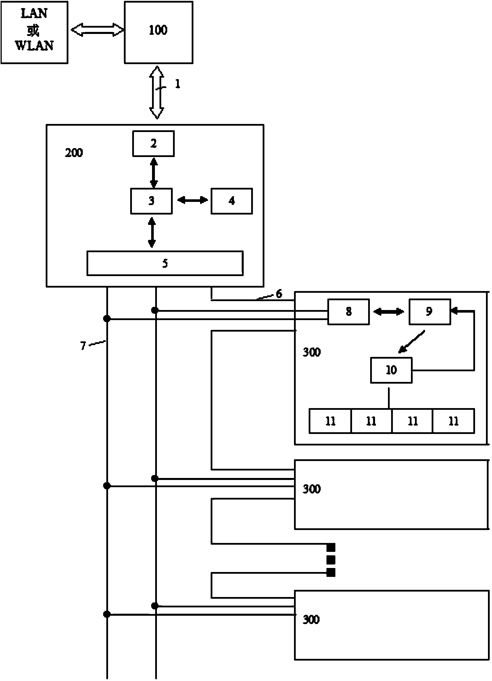
[0032] A point-by-point fault detection method for a bus-based LED display system, which is based on a parallel-based bus-based LED lighting control system. Such as figure 1 As shown: the LED lighting control system based on the parallel basis is composed of a host computer 100, an LED controller 200 and a number of LED lamps 300 controlled in parallel by the LED controller 200; Connected with the upper computer 100, the LED controller 200 consists of a TCP / IP communication module 2 (such as DM9000AEP, DM9008AEP, etc.), a central processing unit 3 (such as NUC130LE, SAM7S256, SAM7S64, etc.), an information storage module 4 (such as IS61LV5128, IS61LV2568, etc. ) and a first communication module 5 (such as MAX1487, MC3487, SN75176, MC3486, etc.); the LED lamp 300 is composed of a second communication module 8 (such as 6N137, SN75176, MAX1487, etc.) processor and data storage module 9 (such as 51 series , STC11F02 series, STC15W202 series, etc.), display monitoring module 10 (s...

Embodiment 2

[0039] This embodiment 2 is the application on the basis of the method of embodiment 1, and it further performs the following steps after step A4:

[0040] The fault point information is uploaded to the host computer 100 through the TCP / IP communication module 2, and the fault report is formed by the host computer 100, and transmitted to the end user through LAN or WLAN. In this way, the user can obtain the fault information in a very timely manner, and know the fault location accurately, which is conducive to timely repair and other processing.

Embodiment 3

[0042] This embodiment 3 is the application on the basis of the method of embodiment 1, and it is to further perform the following steps after step A4:

[0043] When the image is displayed, the central processing unit 3 transfers each frame of image data into the memory, reads the stored fault point information of the information storage module 4 at the same time, modifies the image data according to the fault point information, modifies the fault point position data to a black signal value, and modifies The final image information is output to the display module 11 for display through the first communication module 5, communication bus 7, second communication module 8, processor and data storage module 9, and display monitoring module 10, so that the black signal of the fault point is displayed, thereby realizing fault Click shield.

[0044] The application method in the above-mentioned embodiment 3 is an emergency treatment method, and this application can also be used in co...


PUM


Abstract

The invention relates to a bus-system LED display system point-by-point fault detection method and the application thereof. The method is based on a parallel bus-system LED lighting control system. The system is composed of an upper computer, an LED controller and a plurality of LED lamps which are connected in parallel and controlled by the LED controller. The LED controller is connected with the upper computer through an optical fiber or a network cable. The LED controller is composed of a TCP/IP communication module, a center processor, an information storage module (which is selectable) and a first communication module. Each LED lamp is composed of a second communication module, a processor and data storage module, a display monitoring module and a display module, wherein the second communication module of the LED lamp is connected with the first communication module of the LED controller through an address writing line and a communication bus. The system has the functions of remote monitoring, fault detection, fault feedback, automatic fault shielding, brightness adjustment, automatic encoding and the like, and managers can grasp system working conditions immediately; due to the fact that the system has the automatic fault shielding function, fault points are in the perfectly-black state, and damage caused by color loss, flashing and other phenomena on the whole picture vision is avoided.

Description

technical field [0001] The invention relates to a bus-based LED display system, in particular to a point-by-point fault detection method for a bus-based LED display system and its application. Background technique [0002] With the rapid development of LED technology in recent years, more and more LEDs are used in the field of lighting, such as urban landscape lights, but at the same time, some areas or parts of many projects appear to be lack of color, flickering and other phenomena due to faults, which give people visual However, there is currently no emergency response mechanism for such defects. [0003] In addition, once the above-mentioned defects occur, they can only be dealt with after the technician observes the fault and the fault location or someone else reports the fault for repair, and the processing time has been greatly delayed. Contents of the invention [0004] The purpose of the present invention is to provide a point-by-point fault detection method and ...

Claims


Application Information

Patent Timeline
IPC IPC(8): G05B23/02G01R31/44G09G3/32H04L29/06
CPCG05B23/0213G05B23/0289G09G3/32
Inventor 吴建中黄泽准王琳
Owner SHANGHAI GRAND LIGHT
Why Eureka
Try Eureka