Novel high-voltage switch on-off transmission device
A technology of high-voltage switches and transmissions, applied in high-voltage/high-current switches, electric switches, high-voltage air circuit breakers, etc., can solve the problems of violating the miniaturization design of high-voltage circuit breakers, improve the breaking and closing capabilities, reduce Product cost, effect of improving service life
- Summary
- Abstract
- Description
- Claims
- Application Information
AI Technical Summary
Problems solved by technology
Method used
Image
Examples
specific Embodiment approach
[0029] The preferred embodiment of the novel high-voltage switch switching transmission device of the present invention is:
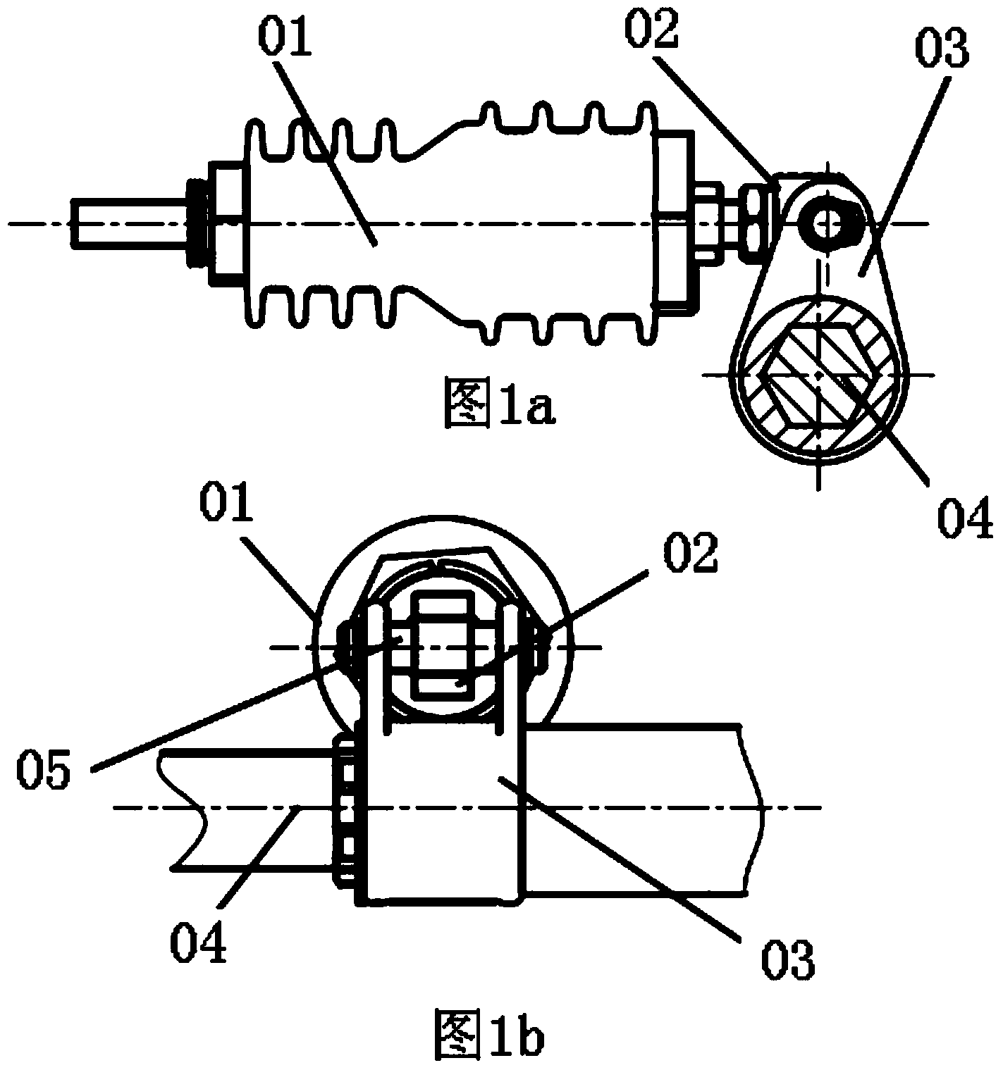
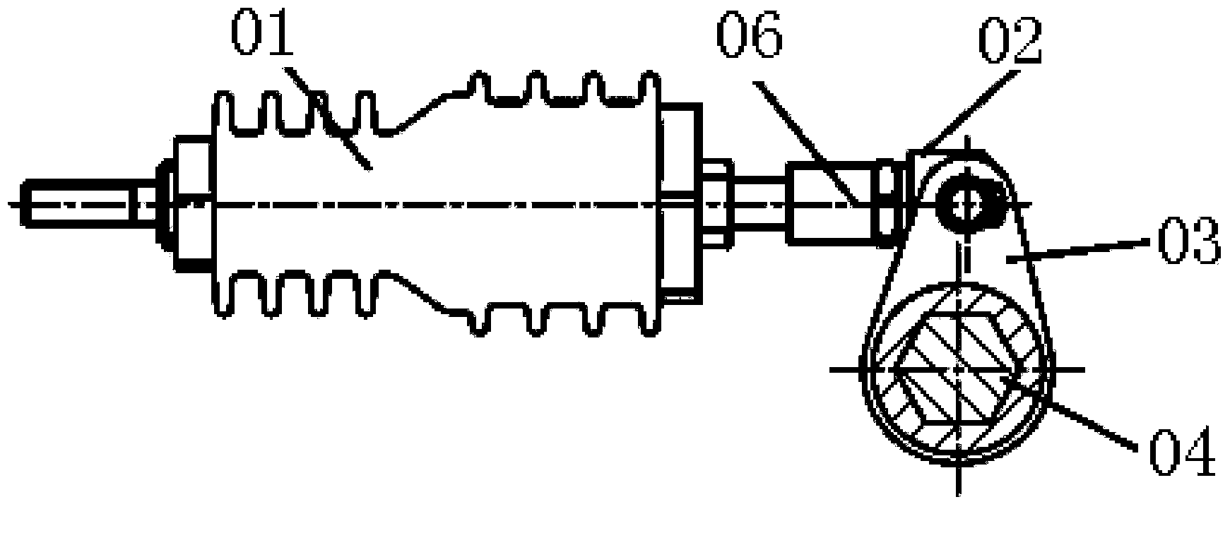
[0030] It includes a main shaft and an insulating pull rod, the main shaft is provided with a crank arm, the outer end of the crank arm is provided with a slider, the insulating pull rod is provided with an insulating pull rod insert, and the insulating pull rod insert is provided with threads. The insulating pull rod insert passes through the central hole of the slider, and the insulating pull rod inserts on both sides of the slider are respectively provided with fixing nuts.
[0031] Both ends of the slider are respectively provided with a shaft head, and the outer end of the crank arm is provided with an oblong hole, and the shaft head is inserted into the oblong hole.
[0032] The slider is provided with a threaded hole for installing the mechanical characteristic detection equipment of the high voltage switch.
[0033] An elastic washer is arrange...
specific Embodiment
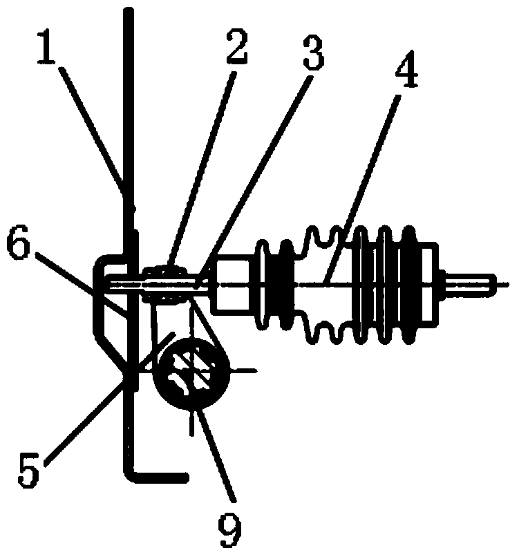
[0036] Such as Figure 3a , Figure 3b , Figure 3c As shown, including: insulating rods, sliders, crank arms, spindles and guide plates, etc. The technical content of specific embodiment is realized through the following measures:
[0037] Arm installation:
[0038] Install the crank arm and bushing on the main shaft (the shape of the crank arm is as follows Figure 5 shown), wherein the crank arm is positioned through the bushing, and the transmission is realized through the spline fit between the crank arm and the main shaft.
[0039] Slider installation:
[0040] Install the slider on the oblong hole of the crank arm, and fix it on the crank arm through the bushing (the shape of the slider is as follows Figure 4a , Figure 4b shown).
[0041] Insulation rod installation:
[0042] Insert the insulating tie rod insert through the center hole of the slider and into the guide hole of the guide plate mounted on the side plate. During the installation process, nuts ar...
PUM
 Abstract
Description
Claims
Application Information
 - R&D
- Intellectual Property
- Life Sciences
- Materials
- Tech Scout
- Unparalleled Data Quality
- Higher Quality Content
- 60% Fewer Hallucinations
Browse by: Latest US Patents, China's latest patents, Technical Efficacy Thesaurus, Application Domain, Technology Topic, Popular Technical Reports.
© 2025 PatSnap. All rights reserved.Legal|Privacy policy|Modern Slavery Act Transparency Statement|Sitemap|About US| Contact US: help@patsnap.com


