Camera module

A camera module and lens technology, which is applied in the electronic field, can solve the problems of unfavorable wide application of camera modules and high cost of camera modules, and achieve the effects of being beneficial to wide application, low cost and high definition

Inactive Publication Date: 2015-01-07
TRULY OPTO ELECTRONICS
View PDF6 Cites 15 Cited by
  • Summary
  • Abstract
  • Description
  • Claims
  • Application Information

AI Technical Summary

Problems solved by technology

[0005] The invention provides a camera module to solve the problem in the prior art that the camera module that adjusts the inclination of the lens through a closed-loop control system has a high cost and is not conducive to the wide application of the camera module

Method used


Image

  • Camera module
  • Camera module
  • Camera module

Examples


Embodiment 1

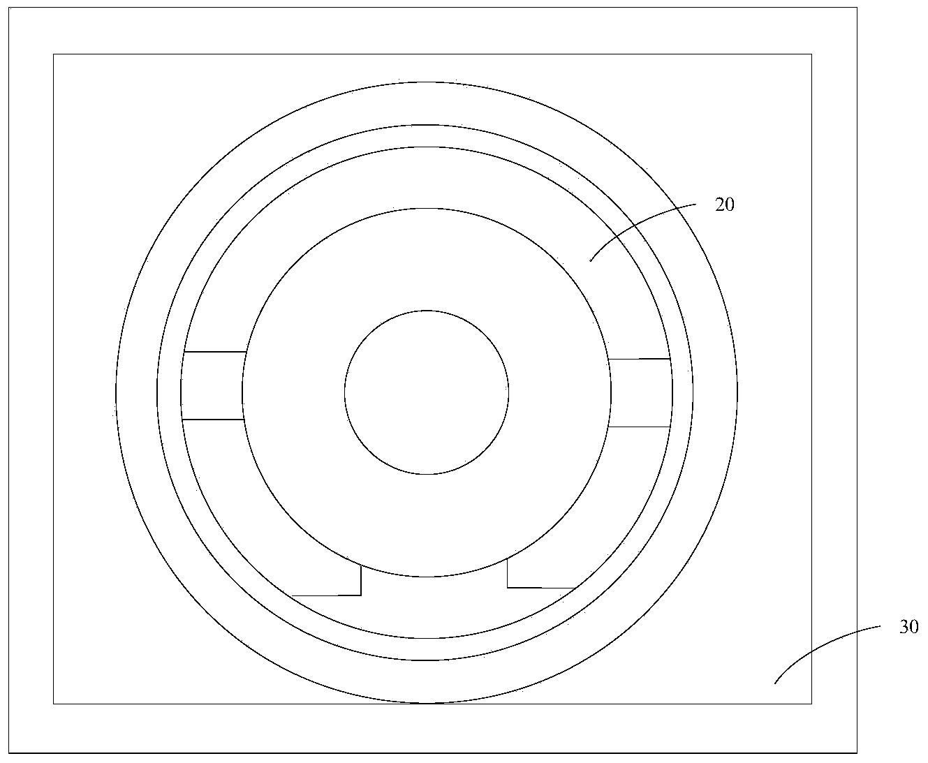
[0038] This embodiment provides a camera module, its plan view is as follows figure 2 As shown, it includes a lens 20 and a motor 30 , wherein the lens 20 includes a lens barrel and a lens fixed inside the lens barrel, and the lens may be one lens or a lens group composed of multiple lenses. The motor 30 can fit the lens 20 and drive the lens 20 to move, so as to realize the focusing function of the camera module.

[0039] In this embodiment, the section view of the camera module is as follows image 3 As shown, the outer side of the lens barrel 201 of the lens 20 has a fixed strip 203, and the fixed strip 203 can continuously go around the lens barrel 201 for a week, and can also be discontinuously arranged on a circle outside the lens barrel 201. In any case, the fixed strip 203 are located on the circumference of a cross section outside the lens barrel 201, of course, the specific position of the fixing bar 203 can be set according to the actual situation, the present inv...

Embodiment 2

[0048] The structure of the camera module provided in this embodiment is substantially the same as that provided in Embodiment 1, the difference is that the inner side of the sleeve of the motor does not have a fixing groove, and the lens is movably fitted in the motor through a fixing bar. The sleeve surface of the motor to adjust the tilt of the lens.

[0049] The sectional structure diagram of the camera module provided in this embodiment, such as Figure 4 As shown, the fixing bar 203 of the lens 20 is movably fitted on the sleeve 31 of the motor, and the lens 20 is supported by the peripheral edges of the sleeve 31 . Since the lens 20 is movable, the inclination between the lens 20 and the photosensitive chip 40 at the bottom can be adjusted.

[0050] The adjustment process of the inclination of the lens 20 is: install the lens 20, the photosensitive chip 40 and the flexible circuit board, etc., and take a test picture, and then adjust the inclination of the lens 20 acco...


PUM


Abstract

The invention provides a camera module. The camera module comprises a camera lens, a motor, a light-sensitive chip and a compensation circuit connected with the light-sensitive chip, wherein the camera lens comprises a lens cone and a lens body fixed to the inside of the lens cone; the motor allows the camera lens to be embedded and can drive the camera lens to move so that focusing of the camera module can be achieved; the light-sensitive chip is used for capturing light rays entering the camera lens and enabling a picture to be formed, and the compensation circuit is used for analyzing the picture and compensating the picture by means of an edge image so that sharpness of the picture can be adjusted; a fixing strip is arranged on the outside of the camera lens, and the camera lens can be movably embedded in the inner side or the surface of a sleeve of the motor through the fixing strip so that inclination of the camera lens and the sharpness of the picture can be adjusted. According to the camera module, the camera lens inclination adjustment mode is easy and convenient to achieve, cost is low and accordingly wide application of the camera module is facilitated.

Description

technical field [0001] The present invention relates to the field of electronic technology, more specifically, to a camera module. Background technique [0002] Currently, camera modules with high pixels or large apertures are particularly sensitive to lens tilt. For example, when the lens is tilted severely, the corners of captured pictures will be blurred. Wherein, the inclination of the lens refers to the angle A between the central axis of the assembled lens 101 and the central axis of the photosensitive chip 102, such as Figure 1a As shown, the larger the included angle A is, the larger the inclination is, and the worse the quality of the captured picture is. [0003] In order to ensure the clarity of the captured pictures, such as Figure 1b As shown, it is necessary to ensure that the lens 101 and the photosensitive chip 102 are parallel to each other. Therefore, in the process of processing the camera module, it is necessary to use special equipment to ensure that ...

Claims


Application Information

Patent Timeline
Patent Type & Authority Applications(China)
IPC IPC(8): H04N5/225G02B7/09G03B13/36
Inventor 高艳朋张露张粦钢肖勇卓秋增李建华
Owner TRULY OPTO ELECTRONICS
Why Eureka
Try Eureka