LED driver, control circuit and LED driving method

A technology of LED driver and circuit, applied in the direction of lamp circuit layout, electric light source, electrical components, etc., can solve the problems of increasing power loss, increasing circuit size and cost, and increasing pressure of power switch, so as to reduce system size and optimize dimming effect

Active Publication Date: 2015-01-07
CHENGDU MONOLITHIC POWER SYST
View PDF9 Cites 7 Cited by
  • Summary
  • Abstract
  • Description
  • Claims
  • Application Information

AI Technical Summary

Problems solved by technology

The first method provides enough latching current by using a large RC circuit, but the large RC circuit increases power loss
The second method increases the input current by increasing the peak current of the power switch to provide sufficient latching current, but this method puts more stress on the power switch and increases circuit size and cost

Method used


Image

  • LED driver, control circuit and LED driving method
  • LED driver, control circuit and LED driving method
  • LED driver, control circuit and LED driving method

Examples


Embodiment Construction

[0017] Specific embodiments of the present invention will be described in detail below, and it should be noted that the embodiments described here are only for illustration, not for limiting the present invention. In the following description, numerous specific details are set forth in order to provide a thorough understanding of the present invention. It will be apparent, however, to one of ordinary skill in the art that these specific details need not be employed to practice the present invention. In other instances, well-known circuits, materials or methods have not been described in detail in order to avoid obscuring the present invention.

[0018] Throughout this specification, reference to "one embodiment," "an embodiment," "an example," or "example" means that a particular feature, structure, or characteristic described in connection with the embodiment or example is included in the present invention. In at least one embodiment. Thus, appearances of the phrases "in on...


PUM


Abstract

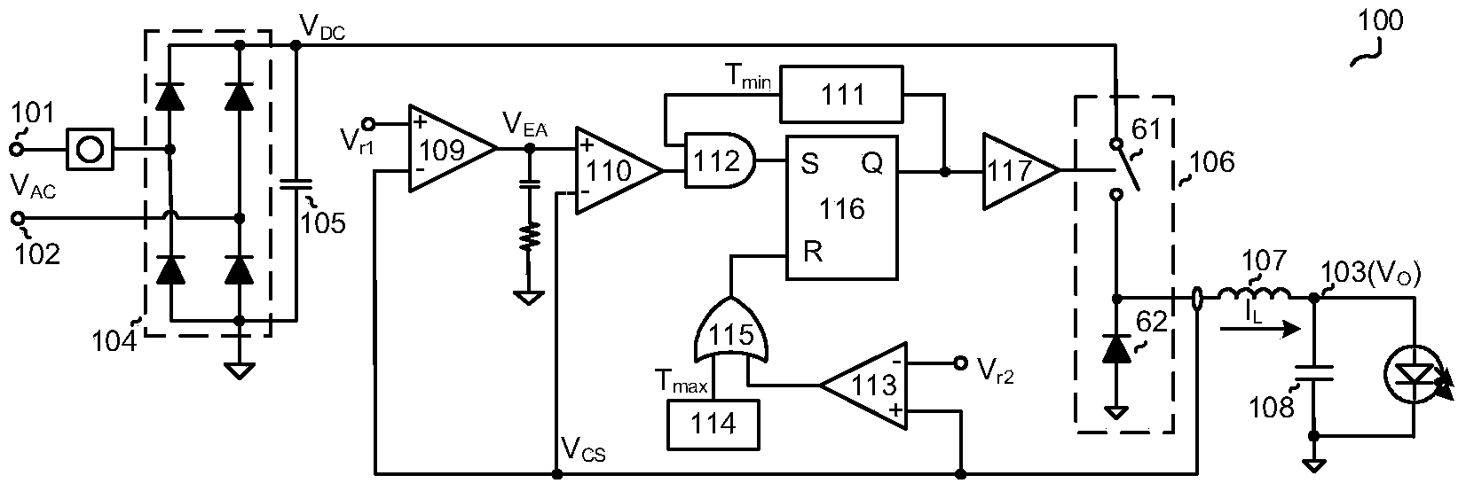
The invention discloses an LED driver, a control circuit and an LED driving method. The LED driver comprises a rectifier, an input capacitor, a power level, an inductor, an error amplifier, a setting comparer, a first timer, a logical AND circuit, a reset comparer, a second timer, a logical OR circuit, an RS trigger and a driving circuit. The LED driver can provide enough latching currents for a triac dimmer without a large RC circuit, the system size is reduced, and dimming is optimized.

Description

technical field [0001] The present invention relates to an electronic circuit, and more specifically, the present invention relates to an LED (light emitting diode) driver, a control circuit and an LED driving method. Background technique [0002] In LED applications, thyristors (thyristors) are commonly used dimmers. In the prior art, LED systems usually work in a boundary conduction mode (BCM). In critical mode, there are generally two ways to shape the input current of the LED driver to optimize the latch current requirement of the TRIAC dimmer. The first method provides sufficient latching current by using a large RC circuit, but the large RC circuit increases power loss. The second method increases the input current by increasing the peak current of the power switch to provide sufficient latching current, but this method puts more stress on the power switch and increases circuit size and cost. Contents of the invention [0003] Therefore, the object of the present ...

Claims


Application Information

Patent Timeline
Patent Type & Authority Applications(China)
IPC IPC(8): H05B37/02H05B44/00
CPCH05B45/10H05B45/3725H05B45/375
Inventor 邝乃兴范子林
Owner CHENGDU MONOLITHIC POWER SYST
Why Eureka
Try Eureka