Driving device, driving method and optical device

A technology for optical equipment and driving signals, applied in optics, projection devices, printing devices, etc., can solve the problems of high power consumption, high frequency, loss of responsiveness of vibration wave motors, etc., to reduce power consumption and suppress abnormal noise. Effect

Active Publication Date: 2016-11-02
NIKON CORP
View PDF11 Cites 0 Cited by
  • Summary
  • Abstract
  • Description
  • Claims
  • Application Information

AI Technical Summary

Problems solved by technology

In the method of gradually changing the phase difference as in Patent Document 1, the responsiveness of the vibration wave motor is impaired.
[0016] (2) When switching the driving direction of the optical system by the vibration wave motor, abnormal noise is a problem
[0018] (4) The above starting frequency is limited to the frequency between the driving frequency and the resonance frequency of the next higher vibration mode of the driving mode, so that too high a frequency cannot be used
In particular, during moving image shooting, swinging action is performed, and the power supply is frequently turned on and off, so that the generation of this abnormal noise is more conspicuous.
[0020] (5) The driving device of Patent Document 6 is always in a state of being supplied with electric power during the control of the vibration actuator, so that there is a problem that the power consumption becomes high.

Method used


Image

  • Driving device, driving method and optical device
  • Driving device, driving method and optical device
  • Driving device, driving method and optical device

Examples


no. 1 approach

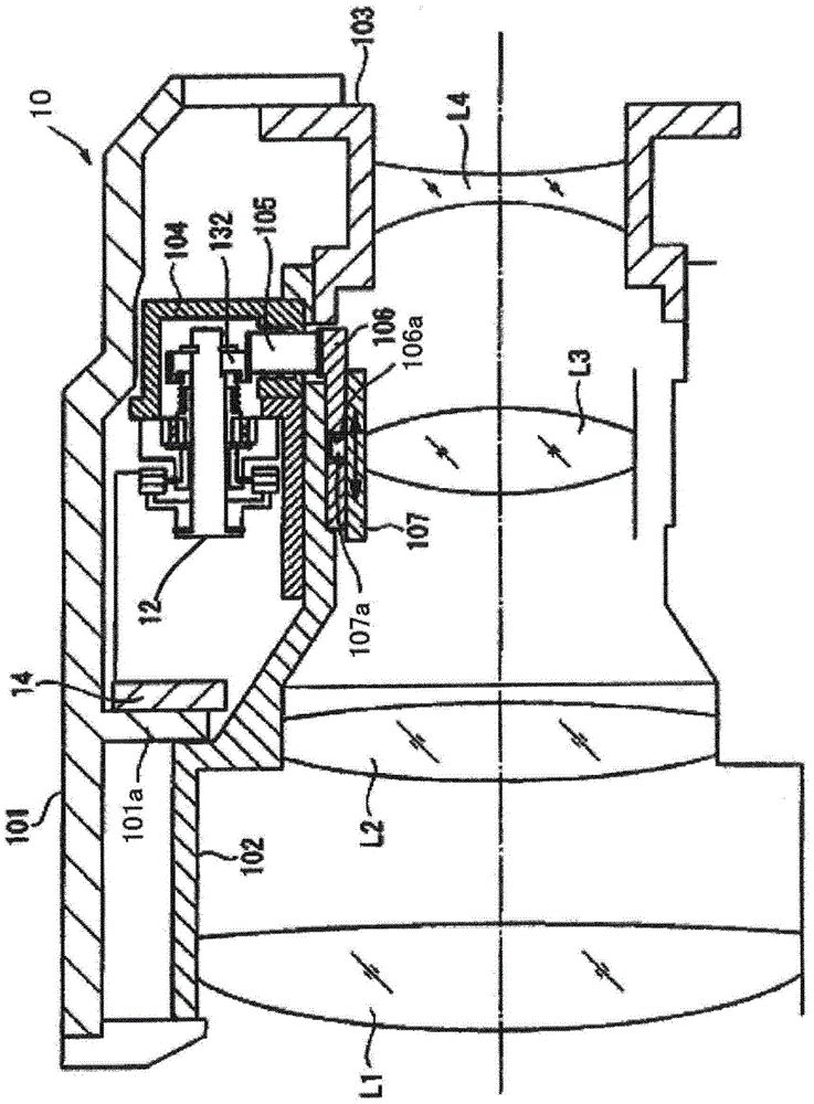
[0081] figure 1 It is a schematic diagram which shows the structure of the lens barrel of 1st Embodiment of this invention. The lens barrel 10 is a lens barrel for an imaging device such as a digital camera. The lens barrel 10 has an outer fixed barrel 101 , a first inner fixed barrel 102 and a second inner fixed barrel 103 . The outer fixing barrel 101 covers the outer peripheral portion of the lens barrel 10 . The first inner fixed cylinder 102 and the second inner fixed cylinder 103 exist on the inner peripheral side of the outer fixed cylinder 101 , the first inner fixed cylinder 102 is located on the subject side, and the second inner fixed cylinder 103 is located on the image side.

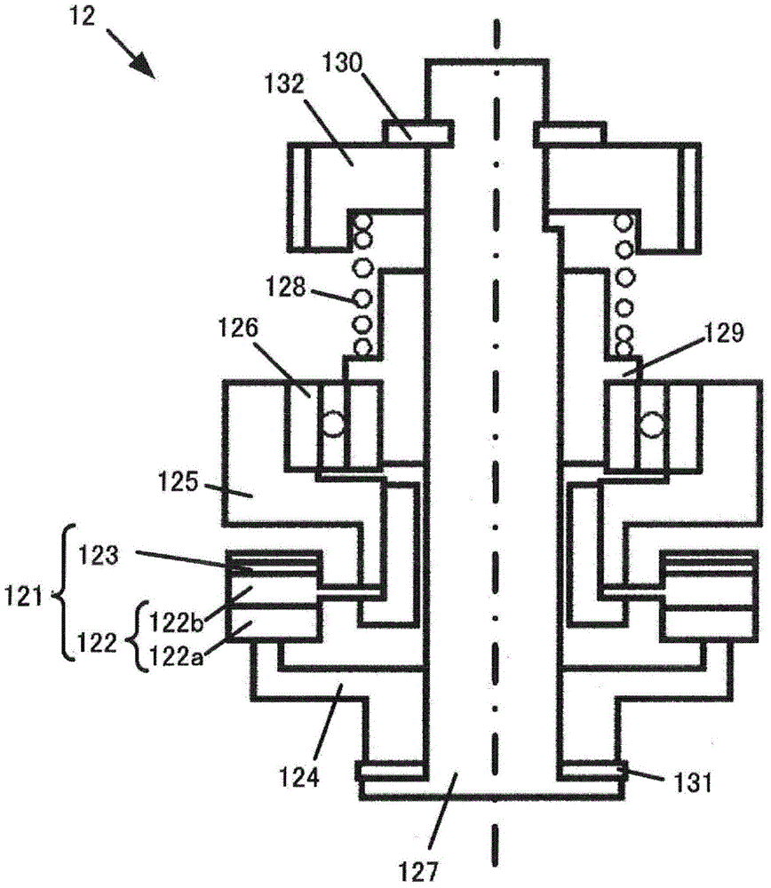
[0082] Between the outer fixed cylinder 101 and the first inner fixed cylinder 102 , a vibration wave motor (vibration actuator) 12 , a driving device 14 and a gear unit module 104 are arranged and fixed on the first inner fixed cylinder 102 . The gear unit module 104 has a reduction gear...

no. 2 approach

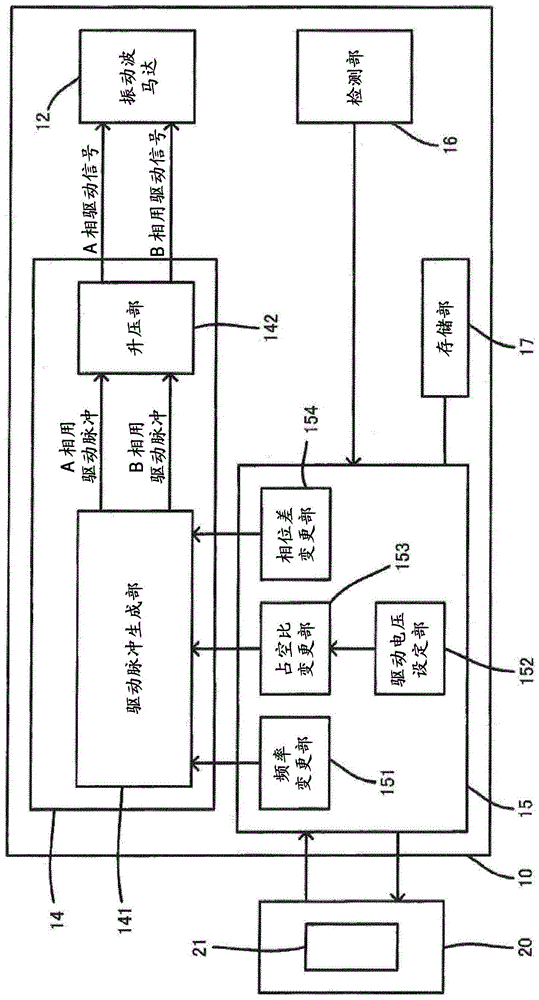
[0128] A second embodiment of the present invention will be described. In the second embodiment, before changing the phase difference, not only the driving voltage is lowered, but also the changing speed of the phase difference is set to be low (the changing speed is slowed down), thereby reducing abnormal noise when the phase difference is changed.

[0129] The range of possible values ​​of the duty ratio of the drive pulse of each phase is limited by the resolution of PWM or the like. For example, the duty ratio of the driving pulse is assigned a set value of 0 to 255, and the set value of the duty ratio cannot be set to a value between "0" and "1". The lower limit of the set value of V1 is determined, for example, by the product of the duty ratio d1 corresponding to the set value "1" and the maximum voltage VMAX of the drive signal.

[0130] The value of VMAX varies depending on the circuit configuration of the drive device of the vibration wave motor 12, the ambient tempe...

Deformed example 1

[0150] In the first embodiment, in the lens-side MCU 15 , the duty ratio changing unit 153 changes the set value of the duty ratio in the drive pulse generating unit 141 . However, the lens-side MCU 15 may include a power supply voltage changing unit 35 - 3 instead of the duty ratio changing unit 153 . In addition, in the second embodiment, in the lens-side MCU 35 , the power supply voltage changing unit 35 - 3 changes the power supply voltage of the booster unit 142 . However, the lens-side MCU 35 may include a duty ratio changing unit 153 instead of the power supply voltage changing unit 35-3.


PUM


Abstract

Abnormal noise when the phase difference is changed is suppressed without impairing the responsiveness of the vibration wave motor. The lens-side MCU (15) of the lens barrel (10) controls a drive device (14) that outputs A-phase drive signals and B-phase drive signals to the vibration-wave motor and applies drive voltage to the vibration-wave motor (12). The lens-side MCU (15) changes the driving voltage using, for example, a driving voltage setting unit (152) and a duty ratio changing unit (153). In addition, the lens-side MCU (15) has a phase difference changer (154) that changes the phase difference between the A-phase drive signal and the B-phase drive signal. The lens-side MCU (15) changes the driving voltage to Vreg when driving the vibration wave motor (12), and changes the driving voltage to Vreg greater than zero and greater than Vreg when the phase difference changing unit (154) changes the phase difference. Vreg small V1.

Description

technical field [0001] The invention relates to a driving device, a driving method and an optical device. Background technique [0002] (1) Regarding the drive of the vibration wave motor, a technique for suppressing the generation of abnormal noise is known (for example, refer to Patent Document 1). In Patent Document 1, abnormal noise when the vibration wave motor is stopped is suppressed by gradually changing the phase difference between the A-phase drive signal and the B-phase drive signal from 90 deg to 0 deg. [0003] (2) An imaging device is known in which an optical system is driven by an oscillating wave motor to perform processing such as autofocus (Patent Document 2). [0004] (3) The vibration actuator uses the expansion and contraction of the piezoelectric body to generate a traveling vibration wave (hereinafter referred to as traveling wave) on the driving surface of the elastic body. Through this traveling wave, the driving surface generates an elliptical mot...

Claims


Application Information

Patent Timeline
Patent Type & Authority Patents(China)
IPC IPC(8): G02B7/04G02B7/08G02B7/36G03B13/36H01L41/09H04N5/225H04N5/232
CPCG02B7/08G03B3/10H02N2/142H02N2/163G03B13/34H02N2/008G03B2205/0084G02B7/04G02B7/36
Inventor 芦泽隆利大根一泰西原慎二森桶利和
Owner NIKON CORP
Why Eureka
Try Eureka