Engine exhaust treatment apparatus and engine driving type heat pump apparatus

An exhaust treatment device, engine-driven technology, applied in exhaust devices, engine components, engine control and other directions, can solve problems such as abnormal noise and damage to liquid seals

Active Publication Date: 2008-09-17
SANYO ELECTRIC CO LTD
View PDF6 Cites 0 Cited by
  • Summary
  • Abstract
  • Description
  • Claims
  • Application Information

AI Technical Summary

Problems solved by technology

[0006] However, in the existing structure, in the non-condensing environment such as dry season or refrigeration period, the storage amount of condensed water flowing into the neutralizer is reduced, and the so-called Liquid seal, so there is a problem of abnormal noise, etc.

Method used


Image

  • Engine exhaust treatment apparatus and engine driving type heat pump apparatus
  • Engine exhaust treatment apparatus and engine driving type heat pump apparatus
  • Engine exhaust treatment apparatus and engine driving type heat pump apparatus

Examples


Embodiment Construction

[0018] Hereinafter, embodiments of the present invention will be described with reference to the drawings.

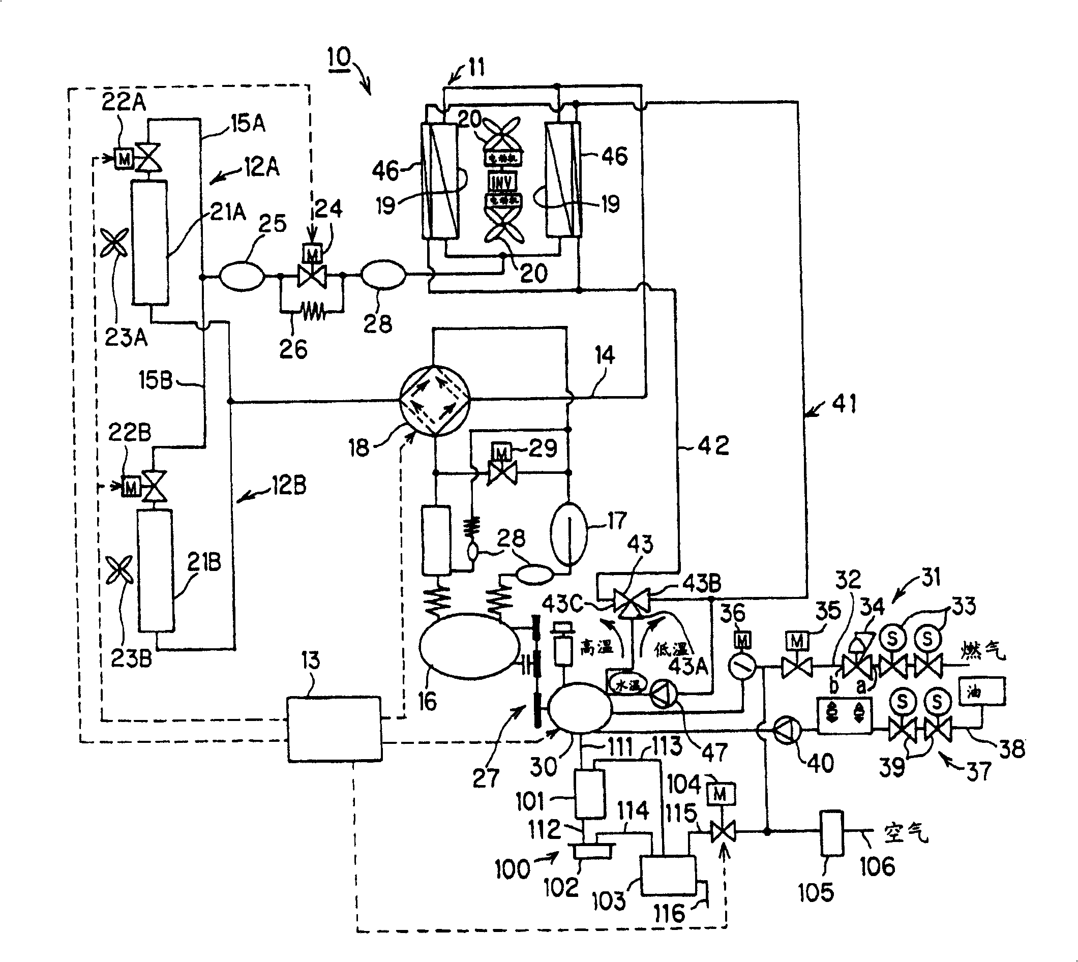
[0019] figure 1 It is a circuit diagram showing a refrigerant circuit in an air-conditioning apparatus to which an embodiment of the engine-driven heat pump apparatus of the present invention is applied.

[0020] Such as figure 1 As shown, the air-conditioning apparatus 10 as a refrigerating apparatus has an outdoor unit 11, a plurality of (for example, two) indoor units 12A, 12B, and a control device 13, and the outdoor refrigerant piping 14 of the outdoor unit 11 and the connections between the indoor units 12A, 12B. The indoor refrigerant pipes 15A and 15B are connected.

[0021] The outdoor unit 11 is installed outdoors, and is configured such that a compressor 16 is disposed on an outdoor refrigerant pipe 14, an accumulator 17 is disposed on the suction side of the compressor 16, and a four-way valve 18 is disposed on the outflow side. On the four-way valve 18 s...


PUM


Abstract

An engine exhaust treatment apparatus for exhausting exhaust gas of an engine (30) from a muffler (101) and an exhaust top (102) and passing condensed water condensed in the muffler (101) and the exhaust top (102) through a neutralizer (103) to neutralize the condensed water is equipped with a return passage (114) for passing the condensed water in the exhaust top to a site in the muffler at which the flow speed of the exhaust gas is higher in the muffler. An engine driving type heat pump apparatus is equipped with the engine heat treatment apparatus.

Description

technical field [0001] The present invention relates to an engine exhaust treatment device having a neutralizer for neutralizing condensed water, and an engine-driven heat pump device using the treatment device. Background technique [0002] Generally, there is known an engine-driven heat pump device in which an engine drives a compressor used in an air conditioner or the like. In this device, in order to treat the exhaust gas of the engine, the exhaust gas of the engine is discharged through the muffler and the exhaust head, and the condensed water condensed in the muffler and the exhaust head is neutralized by the neutralizer. Exhausted exhaust gas treatment device (for example, Patent Document 1). [0003] In the above-mentioned conventional exhaust gas treatment device, there is a muffler return pipe (return passage) for returning the condensed water condensed in the muffler to the neutralizer, and a return pipe (return passage) for returning the condensed water condens...

Claims


Application Information

Patent Timeline
Patent Type & Authority Patents(China)
IPC IPC(8): F02M25/07F28F17/00F01N1/08F01N13/00F01N13/20F01N99/00F24F5/00F25B27/00
CPCF01N3/043Y02T10/16Y02B30/123Y02B30/52Y02T10/20F01N3/005F01N5/02B01D53/92F25B27/00Y02T10/12F01N13/00F02D21/08F02D45/00F28F7/00
Inventor 新井浩士根岸一英土屋嘉朗
Owner SANYO ELECTRIC CO LTD
Why Eureka
Try Eureka