
Adjusting aluminum strip chamfering device

A chamfering device and adjustable technology, which is applied in the field of adjustable aluminum strip chamfering devices, can solve the problems of reducing production efficiency and wasting raw materials, and achieve the effects of improving production efficiency, avoiding repeated stamping, and saving raw materials

Inactive Publication Date: 2015-01-14
SUZHOU JIHONG SCI & TECH
View PDF5 Cites 0 Cited by
  • Summary
  • Abstract
  • Description
  • Claims
  • Application Information

AI Technical Summary

Problems solved by technology

Great waste of raw materials, reducing production efficiency

Method used


Image

  • Adjusting aluminum strip chamfering device

Examples


Embodiment Construction

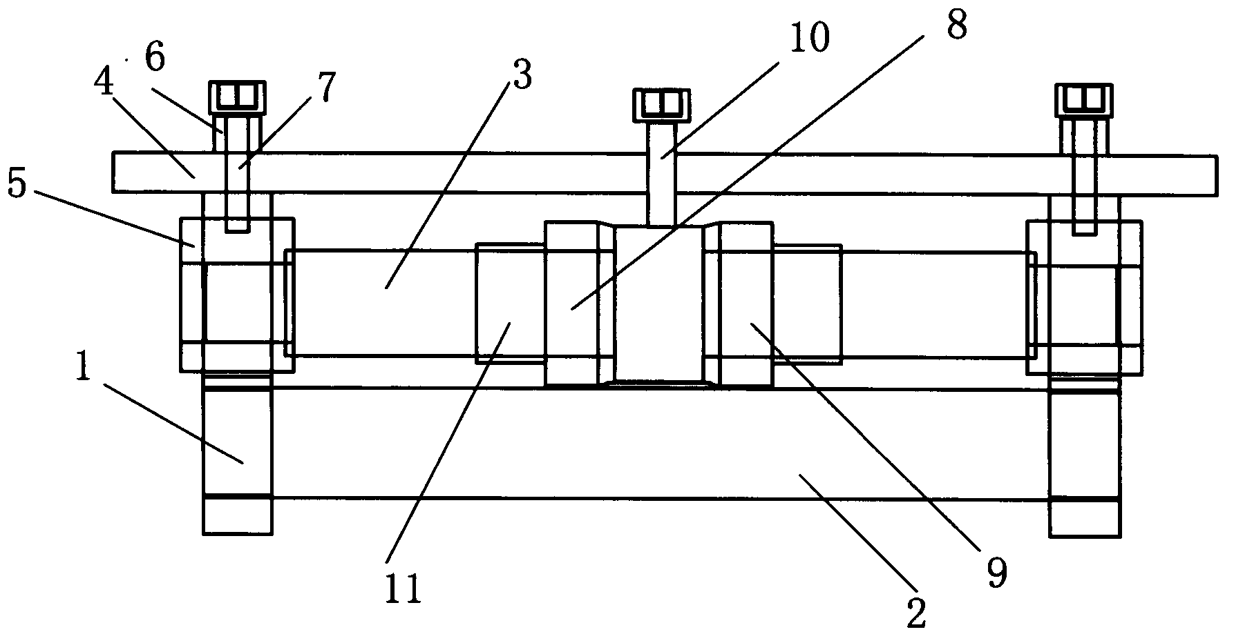
[0018] Such as figure 1 The shown adjustable aluminum strip chamfering device includes a device bracket 1, which is different in that: the device bracket 1 used in the present invention is provided with a lower roller 2. At the same time, a central shaft 3 is arranged above the lower roller 2 , and an upper pressing plate 4 is arranged above the central shaft 3 . Thus, a chamfering processing area is formed between the lower roller 2 and the central shaft 3, which facilitates the processing of the aluminum strip. Moreover, in order to be able to adjust in real time with different working conditions and usage requirements, and realize the implementation of multiple specifications of the same chamfering device, both ends of the central axis 3 are provided with side adjustment components. Of course, considering the multi-directionality of the adjustment, a central adjustment assembly is also provided in the middle of the central axis 3 .

[0019] According to a preferred embodi...


PUM

PropertyMeasurementUnit
thicknessaaaaaaaaaa

Abstract

The invention relates to an adjusting aluminum strip chamfering device which comprises a device support. The adjusting aluminum strip chamfering device is characterized in that a lower roller is arranged on the device support and a center shaft is arranged above the lower roller. Meanwhile, an upper pressing board is arranged above the center shaft, side adjusting assemblies are arranged at the two ends of the center shaft respectively, and a center adjusting assembly is arranged in the middle of the center shaft. Thus, an aluminum strip is chamfered continuously, a lower die plate and a chamfering die do not need to be detached in the whole chamfering process, and the aluminum strip is chamfered conveniently; a repeated stamping phenomenon is avoided and secondary stamping marks at the tail end of a single sheet are eliminated; when the aluminum strip is stamped and cut off, a 2 mm cutting margin does not need to be reserved on the single edge of the aluminum strip, raw materials are saved, and the production efficiency is improved.

Description

technical field [0001] The invention relates to a chamfering device, in particular to an adjustable aluminum strip chamfering device. Background technique [0002] The chamfering of the aluminum strip is for the convenience of assembling the round formed product. Generally, the existing operation method is to punch out the chamfer at the same time when stamping. The width of the chamfer and the angle of the chamfer are completely determined by the mold. When replacing punching products, the lower template and chamfering mold of the punching machine must be disassembled, which is inconvenient to operate. This process has repeated stamping when stamping and chamfering, and there are secondary stamping marks at the end of a single sheet, which affects assembly and appearance. And when punching and cutting, a 2mm cutting amount must be reserved on one side of the aluminum material to prevent one side from being chamfered during punching. Great waste of raw materials reduces pr...

Claims


Application Information

Patent Timeline
Patent Type & Authority Applications(China)
IPC IPC(8): B21D28/02
CPCB21D28/02
Inventor 王澄江
Owner SUZHOU JIHONG SCI & TECH
Learn More