
Magnetic material chamfering system and chamfering method

A technology of chamfering and magnetic materials, which is applied in the manufacture of inductors/transformers/magnets, grinding machines, electrical components, etc. It can solve the problems of difficult control of chamfering size, difficulty in adjustment, and difficult operation of chamfering, and achieve the adjustment time of the whole machine Short, easy chamfer adjustment, good production continuity

Pending Publication Date: 2022-04-01
烟台力凯数控科技有限公司
View PDF0 Cites 0 Cited by
  • Summary
  • Abstract
  • Description
  • Claims
  • Application Information

AI Technical Summary

Problems solved by technology

[0003] When chamfering small corners (less than 0.3mm), the existing chamfering equipment uses electroplated grinding wheels for chamfering. The grinding wheel is directly connected to the motor, and one side is chamfered on the magnetic block track at a time. Four identical The mechanism completes the chamfering process of the four sides in sequence; when adjusting the chamfering angle, the whole set of equipment needs to be adjusted together, which is difficult to adjust, and the size of the chamfering is difficult to control
When chamfering large corners (about 0.3-0.8mm), the magnetic block is generally larger. One is to use a grinding wheel to chamfer on one side (same as the principle of chamfering small corners), and the other is to manually chamfer, resulting in low efficiency and difficult chamfering operations.

Method used


Image

  • Magnetic material chamfering system and chamfering method
  • Magnetic material chamfering system and chamfering method
  • Magnetic material chamfering system and chamfering method

Examples


Embodiment Construction

[0051] In order to make the purpose, technical solutions and advantages of the embodiments of the present invention clearer, the technical solutions in the embodiments of the present invention will be clearly and completely described below in conjunction with the drawings in the embodiments of the present invention. Obviously, the described embodiments It is a part of embodiments of the present invention, but not all embodiments. Based on the embodiments of the present invention, all other embodiments obtained by persons of ordinary skill in the art without creative efforts fall within the protection scope of the present invention.

[0052] In addition, the term "and / or" in this article is only an association relationship describing associated objects, which means that there may be three relationships, for example, A and / or B, which may mean: A exists alone, A and B exist at the same time, There are three cases of B alone. In addition, the character " / " in this article genera...


PUM


Abstract

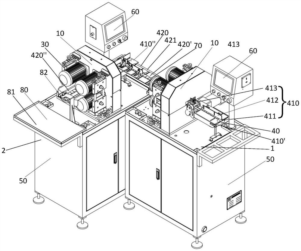
The invention provides a magnetic material chamfering system and method, and the system comprises front-section chamfering equipment which is disposed along a first direction as a feeding direction, and rear-section chamfering equipment which is disposed at the rear section of the front-section chamfering equipment and is disposed along a second direction which is used as the feeding direction and is perpendicular to the first direction. The output end of the front-section chamfering equipment is connected with the input end of the rear-section chamfering equipment, the front-section chamfering equipment and the rear-section chamfering equipment are respectively provided with the chamfering mechanisms, each chamfering mechanism is used for chamfering four edges parallel to the feeding direction, and after a workpiece is chamfered by the front-section chamfering equipment, the chamfering mechanisms are used for chamfering the four edges parallel to the feeding direction. And the direction of the workpiece is not changed, and the workpiece is conveyed to the rear-section chamfering equipment from the input end of the rear-section chamfering equipment to be chamfered. The chamfering precision is high, the chamfering distance is shortened, arrangement is more compact, the chamfering efficiency is high, chamfering adjustment is more convenient, the whole machine adjustment time is short, tools can be conveniently and rapidly replaced, and consumed time is less.

Description

technical field [0001] The present invention relates to the technical field of magnetic material chamfering, and more particularly, to a magnetic material chamfering system and a chamfering method. Background technique [0002] In the processing technology of magnetic materials, after the cutting process, the right-angled edges need to be chamfered. [0003] When chamfering small corners (below 0.3mm), the existing chamfering equipment uses electroplated grinding wheels for chamfering. The grinding wheel is directly connected to the motor, and one edge is chamfered on the magnetic block track at a time. Four identical The mechanism completes the chamfering process of the four sides in sequence; when adjusting the chamfering angle, the whole set of equipment needs to be adjusted together, which is difficult to adjust and the size of the chamfering is difficult to control. When chamfering large corners (about 0.3-0.8mm), the magnetic block is generally larger. One is to use a...

Claims


Application Information

Patent Timeline
Patent Type & Authority Applications(China)
IPC IPC(8): B24B9/02B24B41/00B24B27/00B24B55/00B24B55/02B24B27/02B24B55/06H01F41/02
Inventor 吕春哲王利孙旭东张艳磊冯兴王明郑佳凯车美威郭迎君
Owner 烟台力凯数控科技有限公司
Learn More