Filling device, filling machine and method for filling container

A technology of filling device and filling machine, which is applied in the direction of bottling machine, filling device cleaning, packaging, etc., and can solve heavy problems

Active Publication Date: 2015-01-14
SMI SPA
View PDF8 Cites 7 Cited by
  • Summary
  • Abstract
  • Description
  • Claims
  • Application Information

AI Technical Summary

Problems solved by technology

However, due to the considerable volume that must be kept under control, this solution (even if it is widely used) is onerous...

Method used


Image

  • Filling device, filling machine and method for filling container
  • Filling device, filling machine and method for filling container
  • Filling device, filling machine and method for filling container

Examples


Embodiment Construction

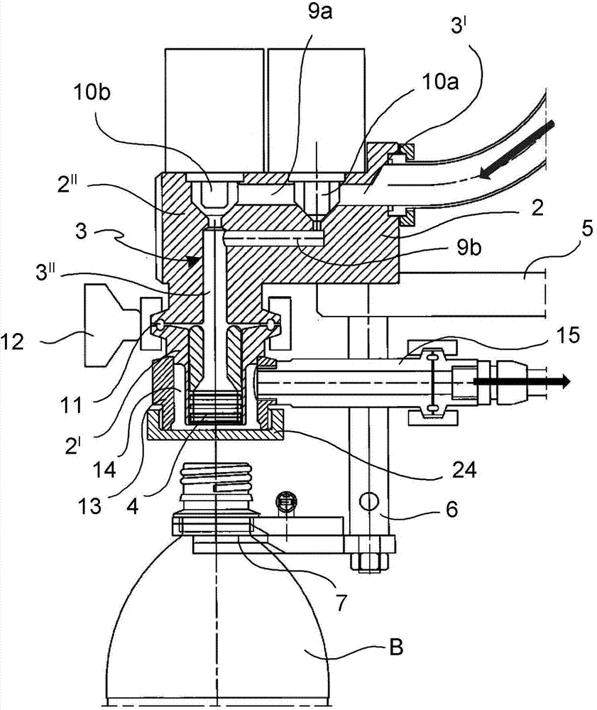
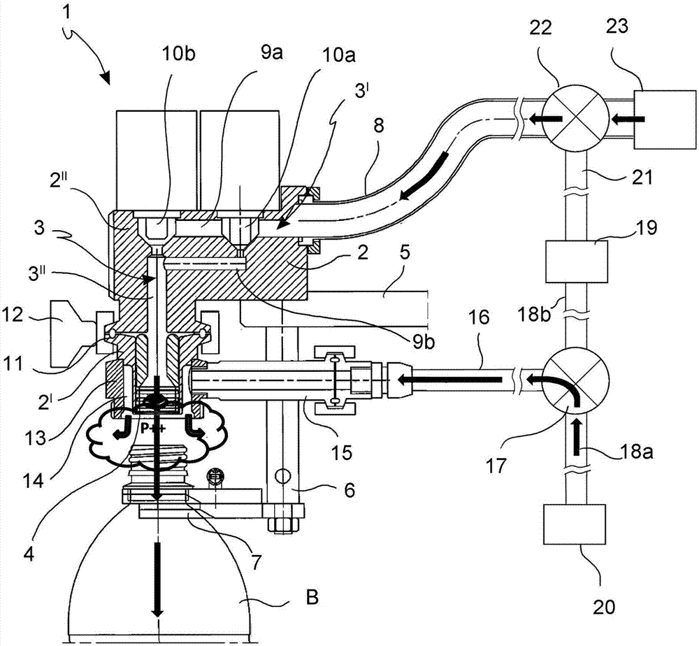
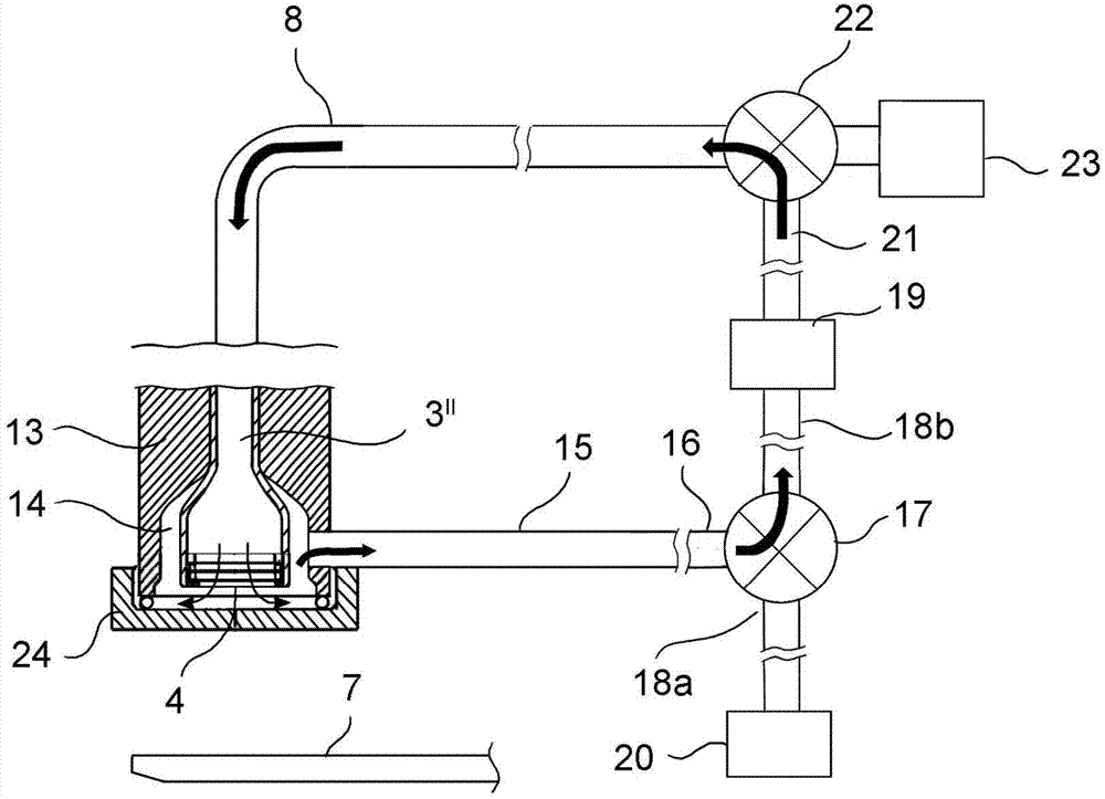
[0016] With reference to the accompanying drawings, the filling device according to the invention, indicated generally by the numeral 1 , comprises a body 2 in which a distribution duct 3 for the filling fluid is obtained. The distribution duct 3 terminates in the lower part with a distribution nozzle 4 .

[0017] The body 2 is fixed to the filling machine (not shown) by means of support rods 5 . The support arm 6 for the bottle B is also fixed to the support rod 5 . The support arm 6 is L-shaped and terminates in a fork 7 capable of engaging the neck of the bottle B .

[0018] The distribution pipe 3 is connected to a filling fluid supply pipe 8 .

[0019] In some embodiments, the distribution duct 3 comprises a first substantially horizontal section 3' and a second vertical section 3" leading to the distribution nozzle 4. In some embodiments, the first section 3' comprises two Two substantially parallel branches 9a, 9b cut off by the valve means 10a, 10b. The two branches...


PUM


Abstract

The present invention relates to a filling device for food product packaging plants in special containers. Particularly, the invention relates to a filling device of the electronic type, in which a contact between the valve and the container to be filled does not occur. Specifically, the invention relates to the beverage bottling field. Particularly, the present invention relates to a filling device (1) comprising a valve body (2) in which a dispensing duct (3) for a filling fluid is obtained, the dispensing duct (3) ending inferiorly with a dispensing nozzle (4), in which the lower portion (2') of the valve body (2) comprises a sleeve (13) surrounding the dispensing nozzle (4), so as to create an annular chamber (14) between the outer surface of the dispensing nozzle (4) and the inner surface of the sleeve (13), characterized in that said sleeve (13) is connected to a sanitization duct (15) which is arranged in flow communication with a source (19) of a gaseous sanitization fluid.

Description

technical field [0001] The invention relates to a filling device for food packaging equipment adapted to containers. In particular, the invention relates to a filling device of the electronic type in which no contact takes place between the valve and the container to be filled. In particular, the invention relates to the field of beverage bottling. Background technique [0002] Prior art filling valves can be of two different types: mechanical valves and electronically controlled valves. [0003] The former generally provide contact between the filling fluid dispensing nozzle and the neck of the bottle, which is necessary to be able to determine the fill level of the bottle and to be able to stop the dispensed flow. A disadvantage of this type of valve is that, for example, in case a bottle becomes contaminated for any reason, this contamination can be transferred to the valve itself and thus to the next container. This is a serious problem because in this field the hygie...

Claims


Application Information

Patent Timeline
IPC IPC(8): B65B55/10B67C7/00
CPCB67C3/282B67C3/002B67C2003/228B67C3/286B67C7/0073B67C3/26
Inventor 里焦·安东尼奥
Owner SMI SPA
Why Eureka
Try Eureka