
Solenoid valve for inflation system

a solenoid valve and inflation system technology, applied in the direction of functional valve types, operating means/releasing devices of valves, safety arrangements of pedestrians/occupants, etc., can solve the problems of main valve maintenanceability, safety compliance, and certain electrical squib initiators, and achieve the effect of preventing external contamination

Active Publication Date: 2018-08-16
THE BF GOODRICH CO
View PDF9 Cites 2 Cited by
  • Summary
  • Abstract
  • Description
  • Claims
  • Application Information

AI Technical Summary

Benefits of technology

The patent text describes a solenoid valve that has a seal and a filter to prevent fluid leakage and external contamination. The valve also allows for pressure balancing and venting of leaked fluid. The technical effect of this invention is to improve the performance and reliability of solenoid valves in various applications.

Problems solved by technology

This leads to electrical squib initiators having certain disadvantages, such as being single shot devices and having main valve maintainability issues and safety compliance issues.

Method used


Image

  • Solenoid valve for inflation system
  • Solenoid valve for inflation system
  • Solenoid valve for inflation system

Examples


Embodiment Construction

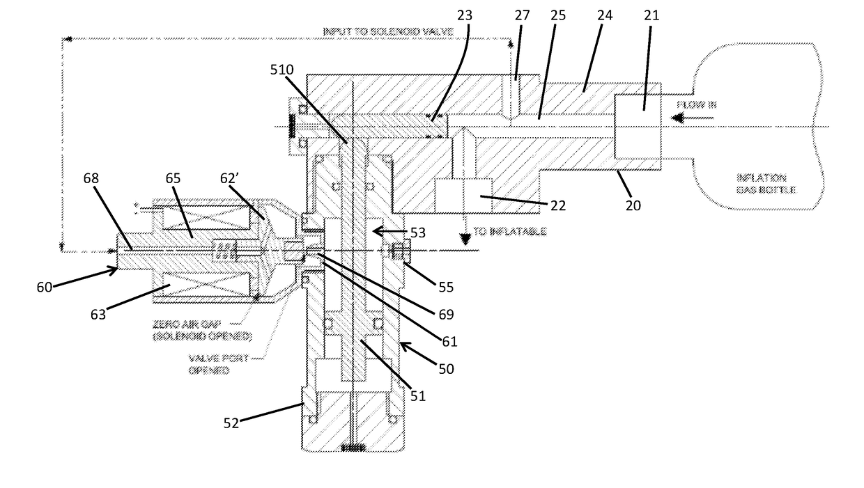
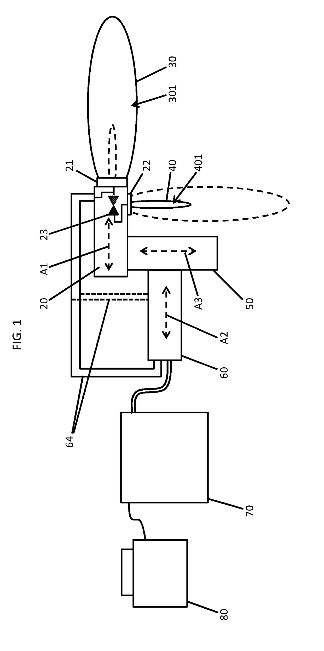
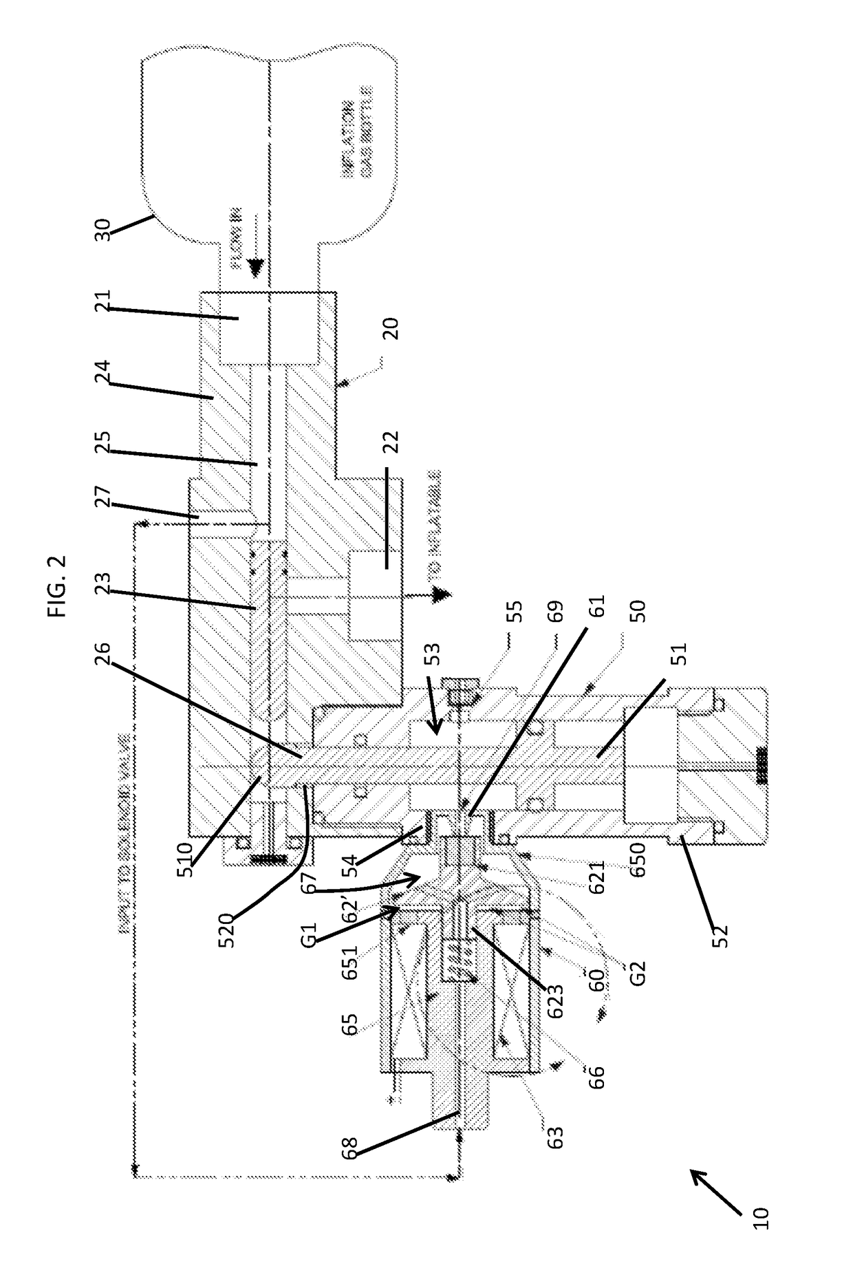
[0037]As will be described below, a fast acting and non-explosive initiator is provided and can be retro-fitted into an inflation system as a replacement for an electrical squib initiator. The fast acting and non-explosive electrical initiator is repeatedly usable and provides for consistent and reliable performance to facilitate the maintenance of inflation unit. The fast acting and non-explosive electrical initiator includes a fast acting and normally-closed pneumatic plunger-type or pilot-type solenoid valve that is receptive of high pressure working fluid from an inlet of an inflation valve and employs electro-pneumatic action to admit pneumatic pressurized fluid into an actuator cavity of an inflation valve with electrical control. The interfacing element is the fast acting solenoid with either a flat armature that has two working air gaps or an armature shaft that has a single working air gap, both of which are designed to meet the actuation time of the inflation valve.

[0038]W...


PUM


Abstract

A valve assembly is provided and includes a valve housing, an actuator housing coupled to the valve housing and configured when actuated to open a normally-closed valve element in the valve housing whereby pressurized fluid is permitted to flow through the valve housing and a solenoid valve. The solenoid valve includes an armature-valve element balanced to remain in a closed position and an electromagnet. The electromagnet generates magnetic flux that moves the armature-valve element into an open position such that at least a portion of the pressurized fluid flows into the actuator housing to actuate the actuator housing.

Description

CROSS-REFERENCE TO RELATED APPLICATIONS[0001]This application claims priority to and the benefit of Indian Patent Application No. 201711005086 filed on Feb. 13, 2017, and all the benefits accruing therefrom under 35 U.S.C § 119, the content of which is incorporated herein in its entirety by reference.BACKGROUND OF THE DISCLOSURE[0002]The subject matter disclosed herein relates to inflation systems and, more particularly, to inflation systems with fast acting pressure unbalanced and balanced, plunger-type solenoid valves.[0003]Pneumatic inflation systems often use stored high pressure gas sources to inflate an inflatable element. The stored high pressure gas sources are normally designed to be discharged within a specified time by the opening of an inflation valve that is normally-closed. Some pneumatic inflation systems, such as those employed in helicopter life rafts and floats, make use of inflation valves that are actuated by electrical initiators with explosive materials. Such e...

Claims


Application Information

Patent Timeline
Patent Type & Authority Applications(United States)
IPC IPC(8): F16K15/20F16K31/06F16K15/02
CPCF16K15/20B63C9/01F16K15/025F16K31/0675F16K11/0708F16K24/06F16K31/0655F16K31/42B63C9/18B63C9/24B60R21/268
Inventor JOHN, POLY PUTHURMASILAMANI, JEEVANANDHAM
Owner THE BF GOODRICH CO
Learn More