
A seawater desalination system using waste heat of flue gas

A flue gas waste heat and seawater technology, which is applied in seawater treatment, general water supply conservation, water/sewage treatment, etc., can solve problems such as regular maintenance, easy scaling, and poor heat transfer effect, so as to reduce energy consumption and cost, Efficient utilization and emission reduction effects

Active Publication Date: 2016-02-24
NORTH CHINA POWER ENG
View PDF3 Cites 0 Cited by
  • Summary
  • Abstract
  • Description
  • Claims
  • Application Information

AI Technical Summary

Problems solved by technology

In the field of seawater desalination technology using flue gas waste heat, He Hongzhou and Chen Zhiqiang developed a "new type of high-efficiency seawater desalination evaporator", but its basic principle is still the distillation method, and the indirect heat exchange method between seawater and flue gas is still used. The thermal coefficient is generally lower than 80W / m 2
In addition, the indirect heat exchange method also has the problems of easy scaling, regular maintenance, and poor heat exchange effect after long-term operation

Method used


Image

  • A seawater desalination system using waste heat of flue gas
  • A seawater desalination system using waste heat of flue gas
  • A seawater desalination system using waste heat of flue gas

Examples


Embodiment 1

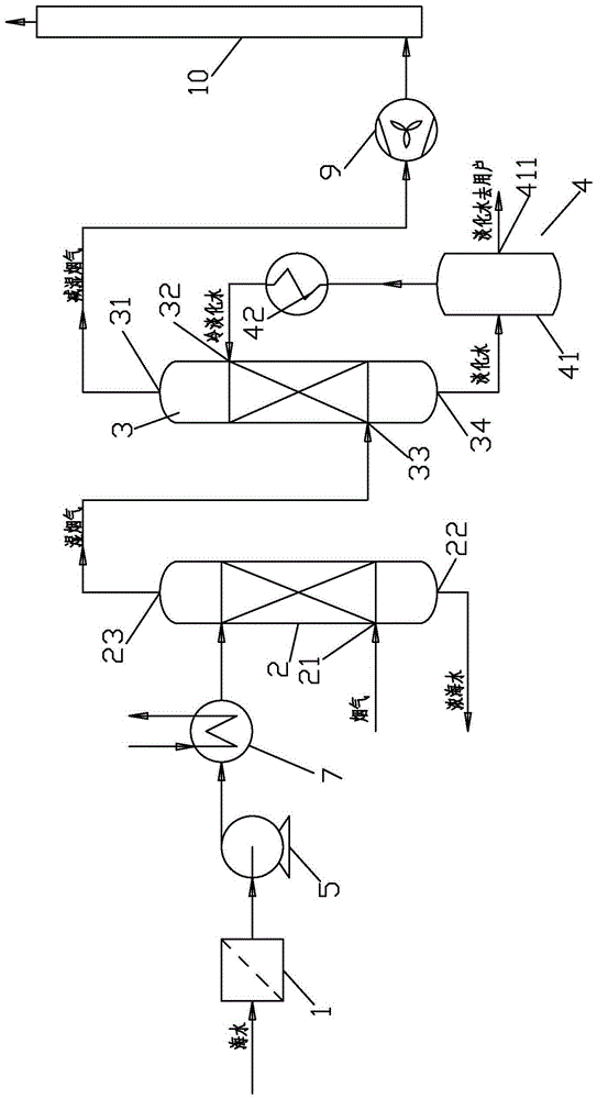
[0034] Embodiment 1: as figure 2 As shown, this embodiment is an integrated waste heat utilization integrated seawater desalination system suitable for thermal power plants. The system includes: seawater filtering device 1 , seawater pump 5 , condenser 7 , humidification tower 2 , dehumidification tower 3 , freshwater storage tank 41 , freshwater cooling device 42 , fan 9 , and chimney 10 .

[0035] In this embodiment, the seawater is pumped to the condenser of the steam turbine by the seawater pump after passing through the filter device for heat exchange; Humidification; after humidification, the flue gas enters the dehumidification tower to reduce temperature and dehumidification, and the water vapor in the flue gas is partially condensed and recovered as desalinated water to the desalination water tank; part of the fresh water in the desalination water tank is used as cooling water after passing through the fresh water cooling device as The cooling water of the dehumidif...

Embodiment 2

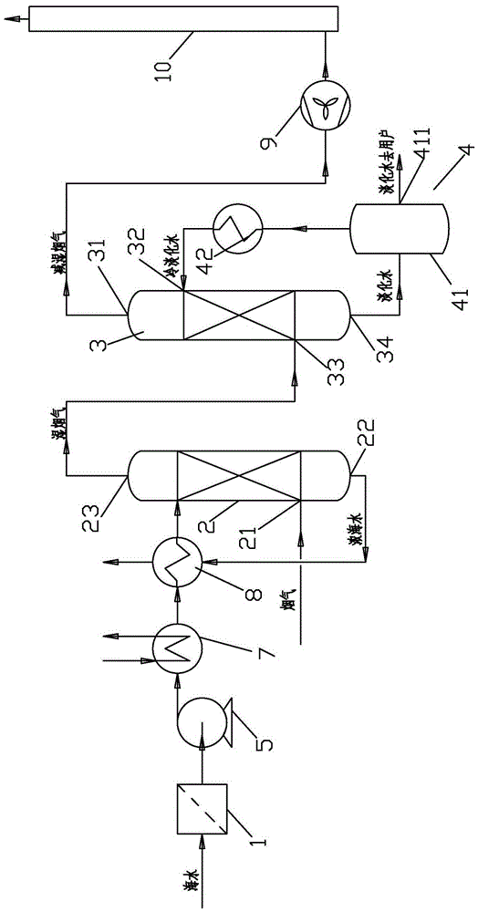
[0037] Embodiment 2: as image 3 As shown, this embodiment is an integrated waste heat utilization integrated seawater desalination system suitable for thermal power plants. The system includes: seawater filtering device 1, seawater pump 5, condenser 7, seawater heat exchanger 8, humidification tower 2, dehumidification tower 3, freshwater storage tank 41, freshwater cooling device 42, fan 9, and chimney 10.

[0038] In this embodiment, the seawater passes through the filter device and is pumped to the steam turbine condenser by the seawater pump for heat exchange; then the seawater enters the thick and light seawater heat exchanger for further heat exchange to increase the seawater temperature; the fully heat-exchanged seawater is sent to the humidification tower The heat and mass transfer is carried out in contact with the flue gas discharged from the boiler, and the flue gas is humidified; after humidification, the flue gas enters the dehumidification tower to reduce temper...

Embodiment 3

[0040] Embodiment 3: as Figure 4 As shown, this embodiment is an integrated waste heat utilization integrated seawater desalination system suitable for thermal power plants. The system includes: seawater filtering device 1, seawater pump 5, condenser 7, seawater heat exchanger 8, humidification tower 2, dehumidification tower 3, freshwater storage tank 41, freshwater cooling device 42, fan 9, and chimney 10.

[0041] In this embodiment, the seawater is sent to the steam turbine condenser) and the fresh water cooling device for heat exchange after passing through the seawater pump through the seawater pump; then the seawater from the seawater condenser enters the thick and light seawater heat exchanger) for further heat exchange to increase the seawater temperature ; After sufficient heat exchange, the seawater is sent to the humidification tower to conduct heat and mass transfer in contact with the flue gas discharged from the boiler to humidify the flue gas; after humidifica...


PUM


Abstract

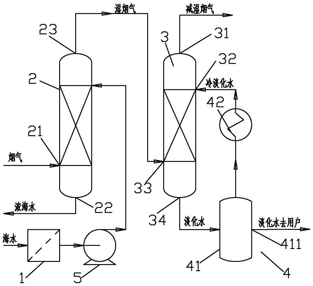
The invention discloses a seawater desalination system capable of making use of afterheat of smoke. The seawater desalination system comprises a seawater filtration device, a humidification tower, a dehumidification tower and a fresh water treatment device which are connected in sequence, wherein the humidification tower is provided with a smoke input opening, and smoke can be introduced into the humidification tower through the smoke input opening; the humidification tower is provided with a concentrated seawater discharging opening, and concentrated seawater can be discharged from the concentrated seawater discharging opening; the humidification tower is provided with a wet smoke discharging opening, and wet smoke can be discharged from the wet smoke discharging opening and conveyed to the dehumidification tower; the dehumidification tower is provided with a smoke discharging opening, and the humidified smoke can be discharged from the smoke discharging opening; the dehumidification tower is provided with a cooling water input opening, and cooling water can enter the dehumidification tower from the cooling water input opening; the dehumidification tower is provided with a wet smoke input opening, and the wet smoke can be discharged from the wet smoke discharging opening and can enter the dehumidification tower from the wet smoke input opening; the dehumidification tower is provided with a fresh water output opening, and fresh water can flow out from the fresh water output opening and reach the fresh water treatment device. The invention provides a system for desalinating the seawater by making use of the afterheat of the smoke and removing pollutants from the smoke.

Description

technical field [0001] The invention belongs to the fields of flue gas waste heat recovery and seawater desalination, in particular to a system for using flue gas waste heat to desalinize seawater. Background technique [0002] my country is a country with serious shortage of energy resources. Per capita remaining recoverable reserves of oil and natural gas are only 7.7% and 7.1% of the world average, and coal, which has relatively abundant reserves, is only 58.6% of the world average. Over the past 30 years of reform and opening up, my country's energy conservation and emission reduction work has achieved great results. Especially in the 21st century, the work of energy conservation and emission reduction has been carried out on a large scale. The new "Energy Conservation Law" has made resource conservation a basic national policy of our country, and energy conservation and emission reduction has become a national and major event involving the participation of the whole so...

Claims


Application Information

Patent Timeline
Patent Type & Authority Patents(China)
IPC IPC(8): C02F1/16C02F9/10B01D47/00B01D53/78
CPCB01D47/00B01D53/60B01D53/78C02F1/048C02F1/16C02F2103/08Y02A20/124
Inventor 鞠付栋聂会建林碧华孙永斌
Owner NORTH CHINA POWER ENG
Learn More