Lifting type hand sample machine
A small prototype, lifting technology, applied in the direction of processing textile material dyeing equipment, processing textile material equipment configuration, etc., can solve the problems affecting the fabric dyeing results, small sample dyeing limitations, fiber bonding, etc., to ensure uniform dyeing and easy to use , the effect of labor saving
- Summary
- Abstract
- Description
- Claims
- Application Information
AI Technical Summary
Problems solved by technology
Method used
Image

Examples
Embodiment 1
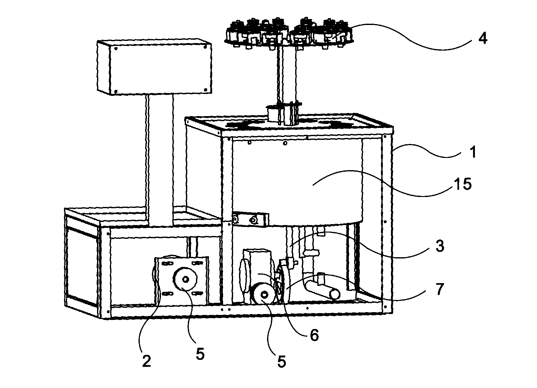
[0019] A lift-type small prototype machine, including a body 1, a speed-regulating motor 2, the speed-regulating motor 2 is arranged under the body 1, the speed-regulating motor 2 drives the lifting shaft 3 to move up and down through the lifting transmission mechanism, and the lifting shaft 3 and the boom lift The rotating disk 4 is fixedly connected, and the boom lifting rotating disk 4 is arranged on the top of the lifting shaft 3, and moves up and down synchronously with the lifting shaft 3; The worm reduction box 6, the worm gear reduction box 6 is connected with the eccentric wheel 7, and the lifting shaft 3 is driven by the eccentric wheel 7 to move up and down.
Embodiment 2
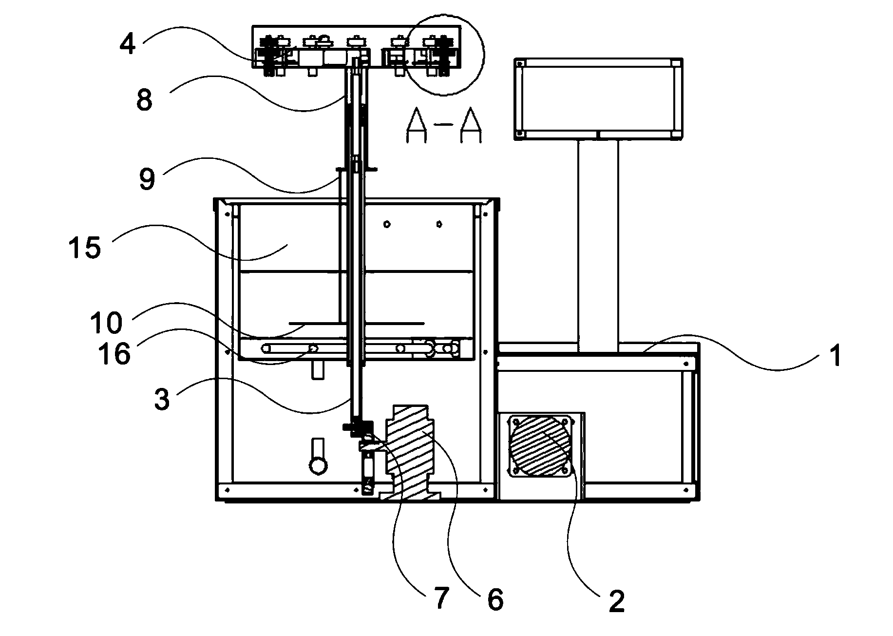
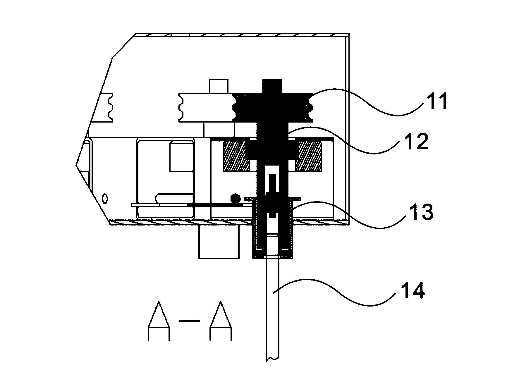
[0021] A lift-type small prototype machine, including a body 1, a speed-regulating motor 2, the speed-regulating motor 2 is arranged under the body 1, the speed-regulating motor 2 drives the lifting shaft 3 to move up and down through the lifting transmission mechanism, and the lifting shaft 3 and the boom lift The rotating disk 4 is fixedly connected, and the boom lifting rotating disk 4 is arranged on the top of the lifting shaft 3, and moves up and down synchronously with the lifting shaft 3; The worm reduction box 6, the worm gear reduction box 6 is connected with the eccentric wheel 7, and the lifting shaft 3 is driven by the eccentric wheel 7 to move up and down; the lower side of the boom lifting rotating disk 4 is connected to the water bath stirring plate connection sleeve 8, and the water bath stirring The disk connection sleeve 8 is connected to the water bath stirring disk connecting rod 9, the water bath stirring disk connecting rod 9 is connected to the water bath...
Embodiment 3
[0023] A lift-type small prototype machine, including a body 1, a speed-regulating motor 2, the speed-regulating motor 2 is arranged under the body 1, the speed-regulating motor 2 drives the lifting shaft 3 to move up and down through the lifting transmission mechanism, and the lifting shaft 3 and the boom lift The rotating disk 4 is fixedly connected, and the boom lifting rotating disk 4 is arranged on the top of the lifting shaft 3, and moves up and down synchronously with the lifting shaft 3; The worm reduction box 6, the worm gear reduction box 6 is connected with the eccentric wheel 7, and the lifting shaft 3 is driven by the eccentric wheel 7 to move up and down; the lower side of the boom lifting rotating disk 4 is connected to the water bath stirring plate connection sleeve 8, and the water bath stirring The disk connection sleeve 8 is connected to the water bath stirring disk connecting rod 9, the water bath stirring disk connecting rod 9 is connected to the water bath...
PUM
 Abstract
Description
Claims
Application Information
 - R&D
- Intellectual Property
- Life Sciences
- Materials
- Tech Scout
- Unparalleled Data Quality
- Higher Quality Content
- 60% Fewer Hallucinations
Browse by: Latest US Patents, China's latest patents, Technical Efficacy Thesaurus, Application Domain, Technology Topic, Popular Technical Reports.
© 2025 PatSnap. All rights reserved.Legal|Privacy policy|Modern Slavery Act Transparency Statement|Sitemap|About US| Contact US: help@patsnap.com