High-temperature high-pressure air flow dyeing machine

An airflow dyeing machine, high temperature and high pressure technology, applied in textile processing machine accessories, liquid/gas/vapor jet propulsion fabrics, textiles and papermaking, etc., can solve the problem of high production costs

Inactive Publication Date: 2008-10-08
唐佳伟
View PDF0 Cites 23 Cited by
  • Summary
  • Abstract
  • Description
  • Claims
  • Application Information

AI Technical Summary

Problems solved by technology

Therefore, the production cost of this temperature a

Method used


Image

  • High-temperature high-pressure air flow dyeing machine
  • High-temperature high-pressure air flow dyeing machine

Examples


Embodiment Construction

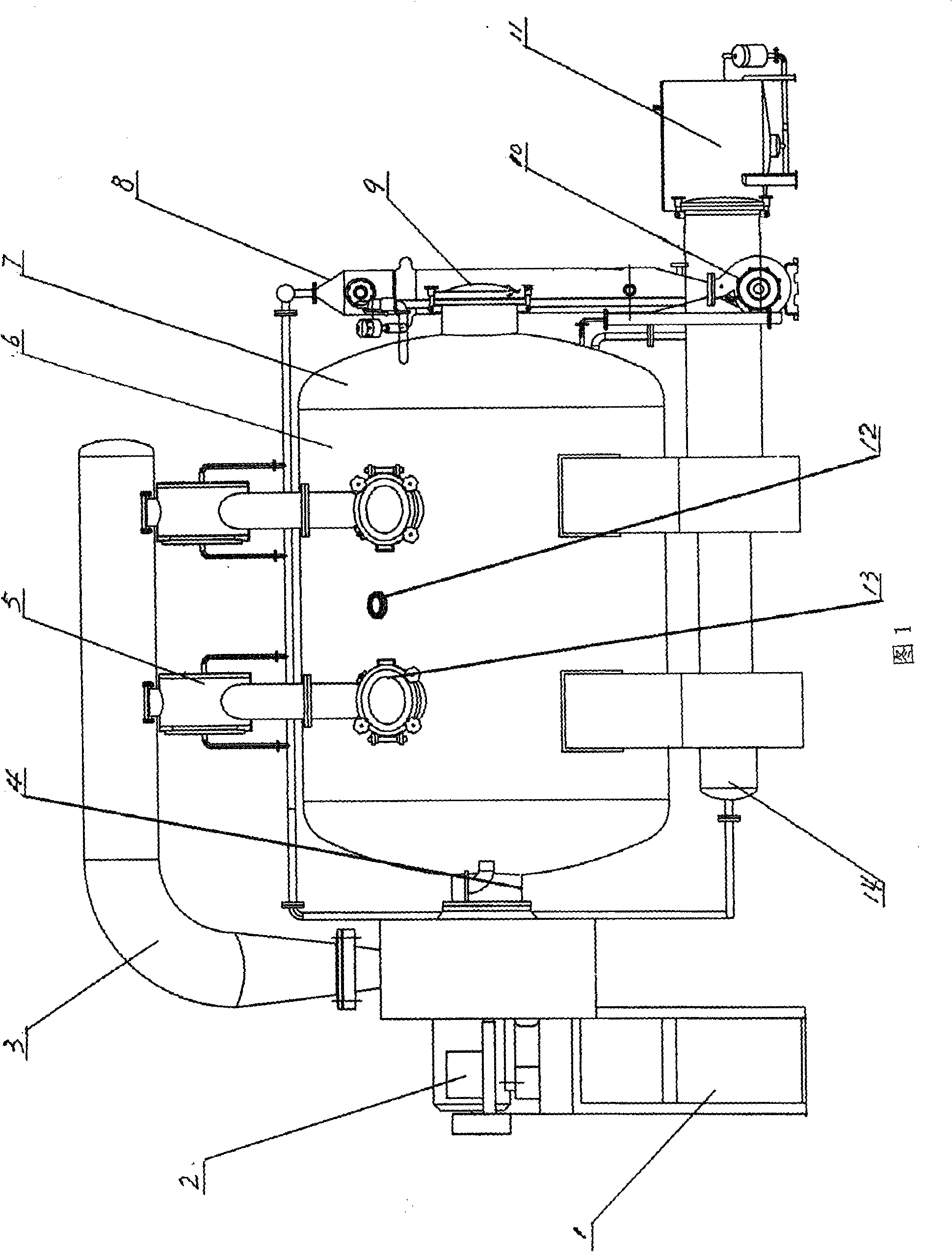
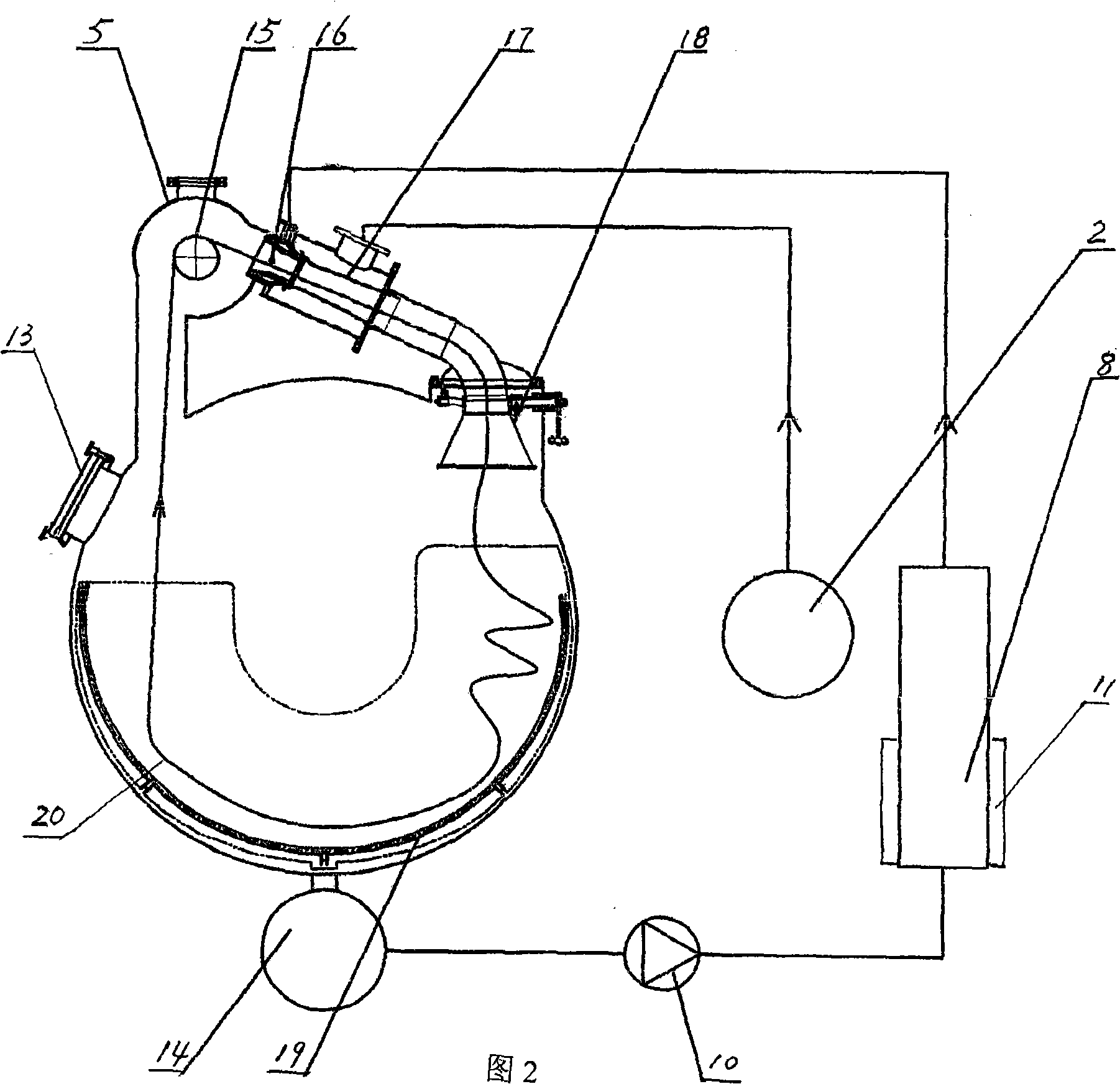
[0010] As shown in FIGS. 1 and 2 , the high-temperature and high-pressure airflow dyeing machine of the present invention includes a cylinder body 6 , a heat exchanger 8 , a fan 2 and a barrel 11 . Wherein, the cylinder body 6 is a closed cylinder, which is arranged horizontally, and an operation hole 13 is processed on the upper wall of the cylinder, and a dyeing tank 19 is processed inside it. The dye tank 19 is circumferentially arranged along the lower half of the inner wall of the cylinder body 6, and two openings are processed on the upper wall of the cylinder body 6 corresponding to the two ends of the dye tank 19, and a swing mechanism 18 is fixed in one of the openings. The effect of swing mechanism 18 is to prevent that dyed fabric 20 knots. A wheel housing 5 is arranged above the opening without the swing mechanism 18, and two ports are processed on the wheel shell 5, one of which communicates with the opening below it through a pipeline, and the other port is conne...


PUM


Abstract

The invention relates to a high temperature and high pressure air flow dyeing machine, in which the high pressure air flow is utilized for the dyeing of textiles after the dyeing atomization, which comprises a cylinder, a lifting wheel, and a feed cylinder and is characterized in that the cylinder is in a horizontal arrangement and internally provided with a dye vat. The upper wall of the cylinder corresponded to both ends of the dye vat is provided with two openings. The inside of one opening is provided with a cloth placing mechanism, and the upper part of the other opening is provided with a wheel shell communicated with the position between two openings through pipelines. The lifting wheel is disposed inside the wheel shell. The inside of the pipeline between the wheel shell and the cloth placing mechanism is provided with a nozzle and a spray head. The outside of the cylinder is provided with a heat exchanger, a feed pump and a fan. The lower part of the cylinder is provided with a backflow mechanism. The heat exchanger is provided with an inlet and an outlet. The outlet thereof is connected to a nozzle through the pipelines, and the inlet thereof is communicated with the feed cylinder, which is communicated to the bottom cavity of the cylinder through the feed pump, the backflow mechanism and the pipelines. The air outlet of the fan is linked with the spray head, and the air inlet of the fan is communicated to the cylinder through an air filter. With the adoption of such a dyeing machine to dye textiles, the production costs can be reduced.

Description

technical field [0001] The invention relates to a high-temperature and high-pressure dyeing machine. Specifically, it is a high-temperature and high-pressure airflow dyeing machine that uses high-pressure airflow to atomize the dyeing solution to achieve fabric dyeing. Background technique [0002] Before the present invention is made, the dyeing machine that is used for fabric dyeing is mainly high temperature and high pressure liquid flow dyeing machine. This high-temperature and high-pressure liquid flow dyeing machine adopts a longer cylinder, which is usually more than 6 meters, and its purpose is to increase the circulation length of the dyed cloth in the dyeing solution and improve the dyeing efficiency. When working, the dyed fabric bypasses the cloth lifting wheel and the nozzle, and then circulates in the dyeing solution in the cylinder through end-to-end connection to form a ring. The circulation power of the fabric is mainly based on the high-pressure water flo...

Claims


Application Information

Patent Timeline
IPC IPC(8): D06B1/02D06B3/28D06B23/00D06B23/14D06B23/20D06B23/22
CPCD06B3/28
Inventor 蒋训军
Owner 唐佳伟
Why Eureka
Try Eureka