Overflow dyeing machine

An overflow dyeing machine and dyeing tank technology, which is applied in the field of overflow dyeing machines, can solve the problems of uneven fabric coloring, unbalanced main pump liquid supply, and unstable speed, so as to prevent fabric surface pollution, prevent nozzle clogging, The effect of improving work efficiency

Inactive Publication Date: 2011-02-02
田立法
View PDF5 Cites 21 Cited by
  • Summary
  • Abstract
  • Description
  • Claims
  • Application Information

AI Technical Summary

Problems solved by technology

[0004] The defect of the above-mentioned traditional overflow dyeing machine is that, in use, when the auxiliary dyestuff or chemical auxiliary agent solution in the material tank 109 is mixed with the dye liquor extracted in the main body 101, in order to avoid the concentration of the dye liquor when it reaches the nozzle 104 Excessive increase will affect the coloring quality, it must be added in a small amount, the addition speed is slow, and it takes a long time
Moreover, supplying auxiliary dye or chemical auxiliary solution at the inlet of the main pump 108 will make the liquid supply of the main pump unbalanced, resulting in unstable speed of the dyeing liquid passing through the nozzle, affecting the dyeing quality
Furthermore, since the dye liquor arriving at each nozzle 104 is transported sequentially by the circulation pipe 107, the conveying paths are inconsistent, so that the amount of dye liquor obtained between each nozzle 104 is uneven, causing uneven coloring of the fabric in each dyeing tank 102.
Due to the contact friction between the fabric, the dye liquor and the pipeline during dyeing, sometimes fibers on the fabric fall off, and adhere to the surface of the fabric together with the insoluble matter in the dye liquor or block the nozzle 104, causing defects in the fabric to be dyed 113 or affecting the dyeing machine normal operation of

Method used


Image

  • Overflow dyeing machine
  • Overflow dyeing machine
  • Overflow dyeing machine

Examples


Embodiment Construction

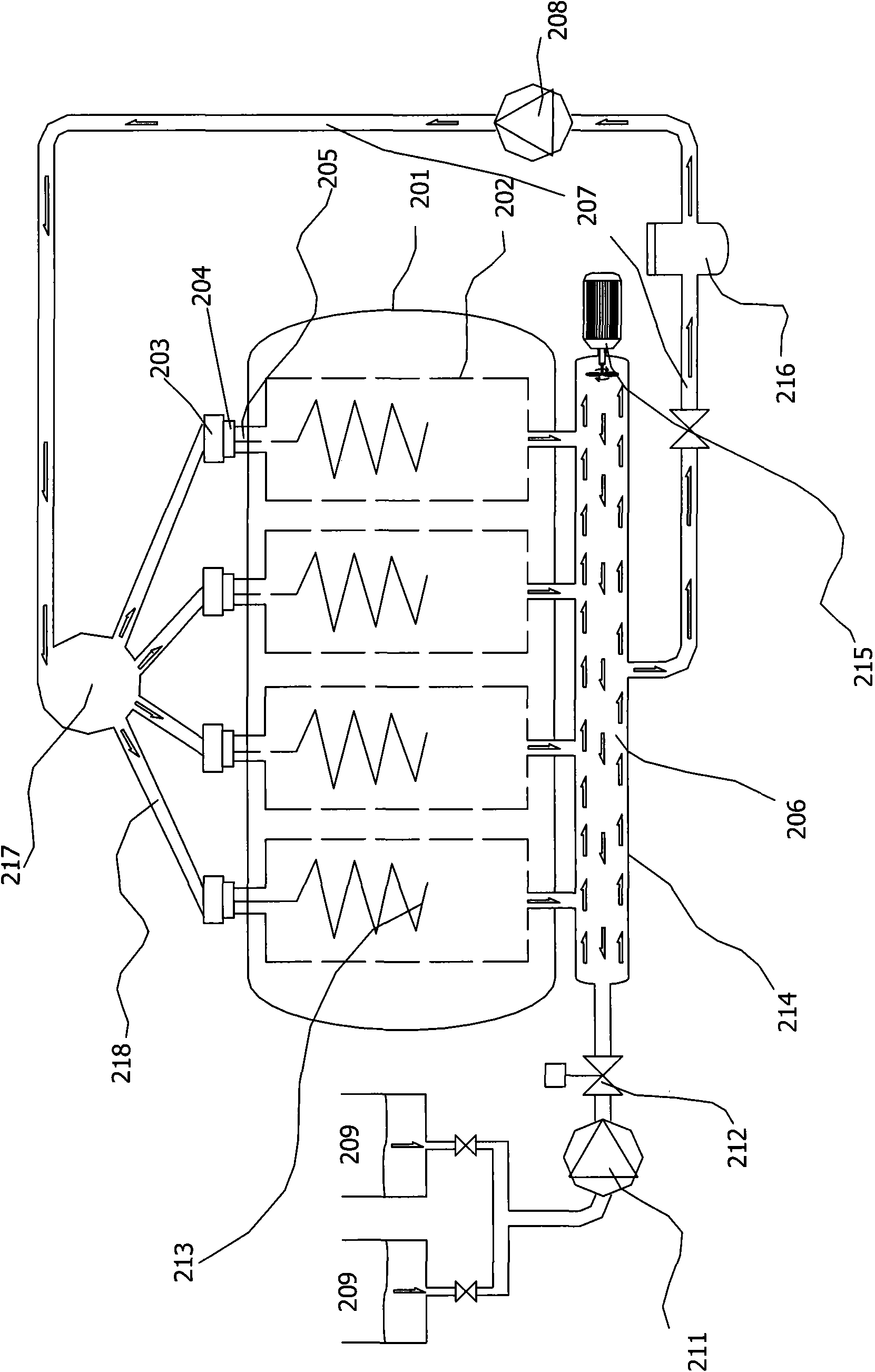
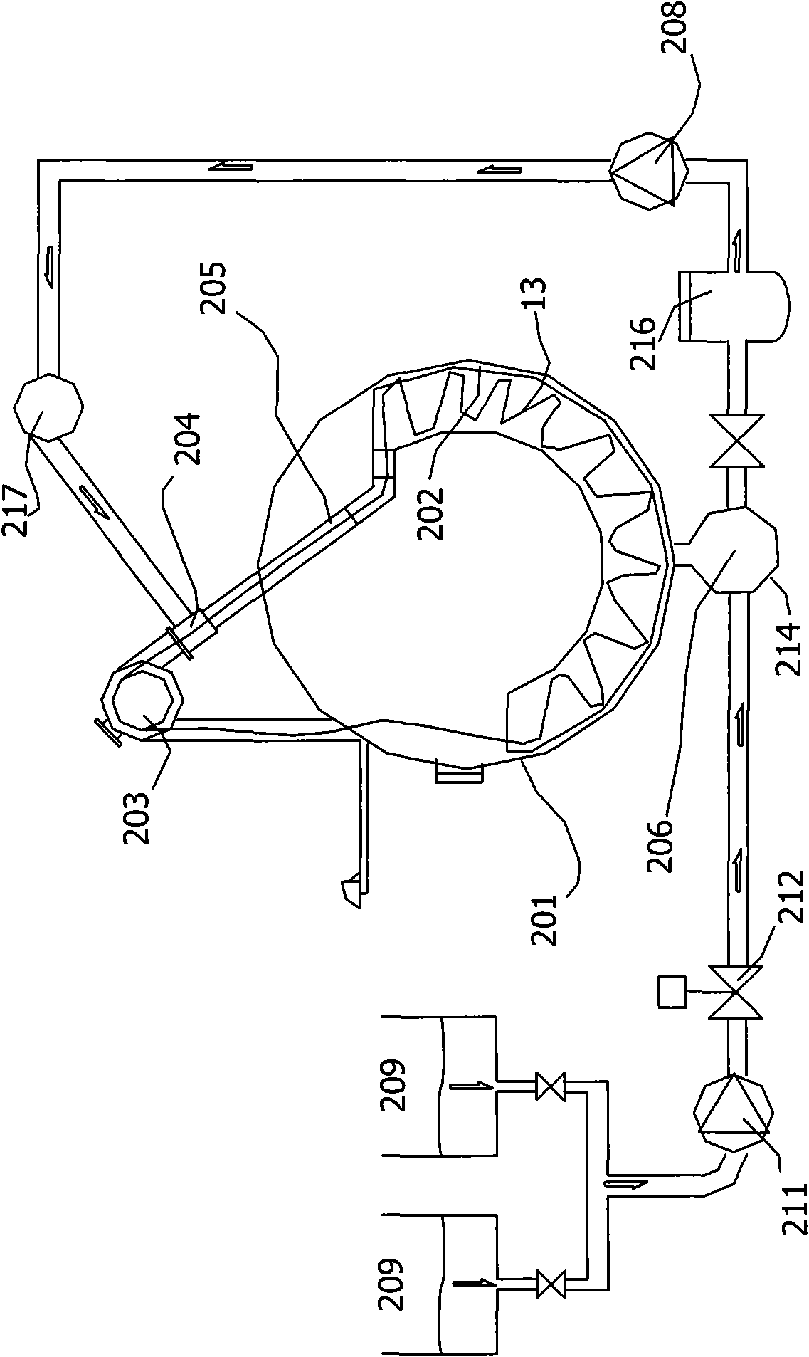
[0020] figure 2 It is a schematic diagram of the overall structure of the overflow dyeing machine of the present invention, image 3 for the invention figure 2 Schematic diagram of the lateral structure. Such as figure 2 and combine image 3 As shown, a kind of overflow dyeing machine provided by the present invention includes a main body 201, a dyeing tank 202 is arranged inside the main body 201, a cloth lifting wheel 203 is arranged outside the main body 201, and a nozzle 204 is arranged above the main body 201, The outlet of the dye tank 202 is connected with the inlet of the nozzle 204 through a circulation pipe 207; the outlet of the chemical material tank 209 is connected with the circulation pipe 207; on the circulation pipe 207, a liquid storage tank 214 is also provided, and the liquid storage tank 214 communicates with the dyeing tank 202, the outlet of the liquid storage tank 214 and the circulation pipeline 207 of the inlet of the nozzle 204 are connected w...


PUM


Abstract

The invention discloses an overflow dyeing machine. The overflow dyeing machine comprises a main machine body (201), wherein a dye vat (202) is arranged in the main machine body (201); a cloth lifting pulley (203) is arranged outside the main machine body (201); nozzles (204) are arranged over the main machine body (201); the outlet of the dye vat (202) is communicated with the inlets of the nozzles (204) through a circulation pipeline (207); the outlet of a chemical material vat (209) is communicated with the circulation pipeline (207); a liquid storage tank (214) is also arranged on the circulation pipeline (207); the liquid storage tank (214) is communicated with the outlet of the chemical material vat (209) and the outlet of the dye vat (202) respectively; and a main pump (208) is arranged on the circulation pipeline (207) which connects the outlet of the liquid storage tank (214) and the inlets of the nozzles (204). The overflow dyeing machine provided by the invention has the advantages that: the structure is simple; a dyeing liquid is uniformly mixed; due to the liquid supply balance among the plurality of nozzles, surface contamination of a fabric and blockage of the nozzles is effectively prevented and dyeing is more uniform; the working efficiency is improved; and the technical time is shortened.

Description

technical field [0001] The invention relates to a dyeing device, in particular to an overflow dyeing machine, which belongs to the technical field of dyeing. Background technique [0002] figure 1 It is a schematic diagram of the structure of a traditional overflow dyeing machine. Such as figure 1 As shown, the existing dyeing machine includes a main body 101 in which a dye solution 106 is contained. A dyeing tank 102 is also arranged in the main body 101 for placing the fabric 113 to be dyed. The top of the main body 101 is equipped with a cloth lifting wheel 103 and a dye solution nozzle 104, and the dye solution nozzle 104 communicates with the dye tank 102 in the main body 101 through the cloth running pipe 105; the main body 101 is equipped with a main pump 108, and the main pump 108 passes through the circulation One end of the pipe 107 communicates with the bottom of the main body 101 , and the other end communicates with the nozzle 104 . The main body 101 is pro...

Claims


Application Information

Patent Timeline
Patent Type & Authority Applications(China)
IPC IPC(8): D06B23/14D06B23/00D06B1/02
CPCD06B3/28D06B23/205
Inventor 田立法
Owner 田立法
Why Eureka
Try Eureka