Display device and source electrode driver thereof

A source driver and display device technology, applied in static indicators, instruments, etc., can solve problems such as increased operating temperature and burnout of parts, and achieve the effect of avoiding burnout

Inactive Publication Date: 2015-01-14
NOVATEK MICROELECTRONICS CORP
View PDF8 Cites 12 Cited by
  • Summary
  • Abstract
  • Description
  • Claims
  • Application Information

AI Technical Summary

Problems solved by technology

However, when the source driver works for a long time, since it continuously provides alternate positive and negative polarity driving voltages to the display panel, the source driver will generate heat to increase its operating temperature.
[0003] Based on the above situation, if the s

Method used


Image

  • Display device and source electrode driver thereof
  • Display device and source electrode driver thereof
  • Display device and source electrode driver thereof

Examples


Example Embodiment

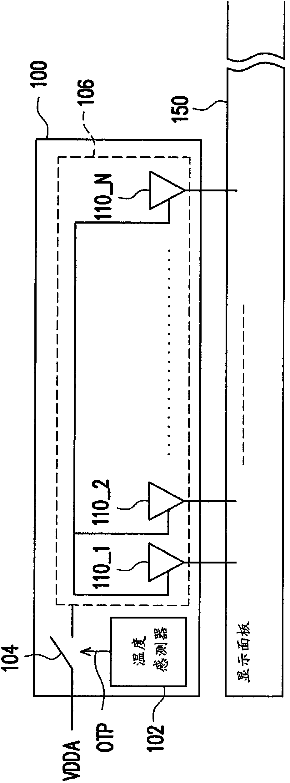
[0035] figure 1 A schematic diagram of the source driver 100 according to the first embodiment of the present invention is shown. Please refer to figure 1 The source driver 100 includes a temperature sensor 102, a power switch 104, and a core circuit 106. The core circuit 106 includes driving voltage generating circuits 110_1 to 110_N for driving the display panel 150. The power switch 104 is coupled to the transmission path through which the core circuit 106 receives the operating power VDDA.

[0036] In this implementation, the temperature sensor 102 performs a detection operation of the operating temperature of the source driver 100 to obtain the operating temperature. The temperature sensor 102 also performs a comparison action between the working temperature and the first preset temperature to generate the over-temperature protection activation signal OTP according to the comparison result. To put it simply, when the temperature sensor 102 compares that the operating temper...


PUM


Abstract

The invention provides a display device and a source electrode driver thereof, wherein the source electrode driver comprises a temperature sensor and a power switch. The temperature sensor is used for measuring a first operation temperature of the source electrode driver, and generates an overtemperature protection starting signal through comparing the first operation temperature with a first preset temperature. The power switch is coupled in a power transmission path of a core circuit of the source electrode driver for receiving the operating power. The power switch switches on or off the power transmission power according to the overtemperature protection starting signal.

Description

technical field [0001] The present invention relates to a source driver and its display device, and in particular to a source driver with temperature sensing capability and its display device. Background technique [0002] In a traditional liquid crystal display (Liquid Crystal Display, LCD), it is often necessary to include multiple source drivers (Source Driver, SD) to generate corresponding driving signals with the gate driver to receive pixel data and output a driving voltage to on the driver display panel. However, when the source driver works for a long time, since it continuously provides alternately switching positive and negative driving voltages to the display panel, the source driver will generate heat to increase its operating temperature. [0003] Based on the above situation, if the source driver of the LCD cannot monitor its own operating temperature and activate the protection function accordingly, the operating temperature of the LCD will continue to increa...

Claims


Application Information

Patent Timeline
IPC IPC(8): G09G3/36G09G3/20
Inventor 陈政宏胡仁杰黄如琳刘益全程智修
Owner NOVATEK MICROELECTRONICS CORP
Why Eureka
Try Eureka