
LED chip mounter

A technology of LED placement machine and placement device, which is applied in the direction of electrical components, printed circuits, printed circuit manufacturing, etc., and can solve the problems of low precision of placement of LED lamp beads, poor flatness of LED light boards, and easy Deformation and other problems, achieve good patch effect, good flatness, and save packaging materials

Active Publication Date: 2015-01-14
深圳市朝阳光科技有限公司
View PDF3 Cites 8 Cited by
  • Summary
  • Abstract
  • Description
  • Claims
  • Application Information

AI Technical Summary

Problems solved by technology

Although the traditional LED placement machine can complete the LED placement process, it still has the following technical defects: 1. In order to ensure the placement quality, this results in low placement efficiency; 2. The placement device absorbs LED lights from the feeding device When the LED lamp beads are placed in the feeding device, there is uncertainty, resulting in low precision of the placement of the LED lamp beads, which affects the quality of the placement; 3. When the feeding device is feeding, it is necessary to carry out the tape loading An intermediate link, which increases the working time, not only leads to low work efficiency, but also increases production costs; 4. When the SMT device puts the LED light board on the light board device for mounting operations, the LED light board is easily deformed, and the LED light The flatness of the board is poor when it is working, resulting in an unsatisfactory patch effect

Method used


Image

  • LED chip mounter
  • LED chip mounter
  • LED chip mounter

Examples


Embodiment Construction

[0045] The present invention will be further described below in conjunction with drawings and embodiments.

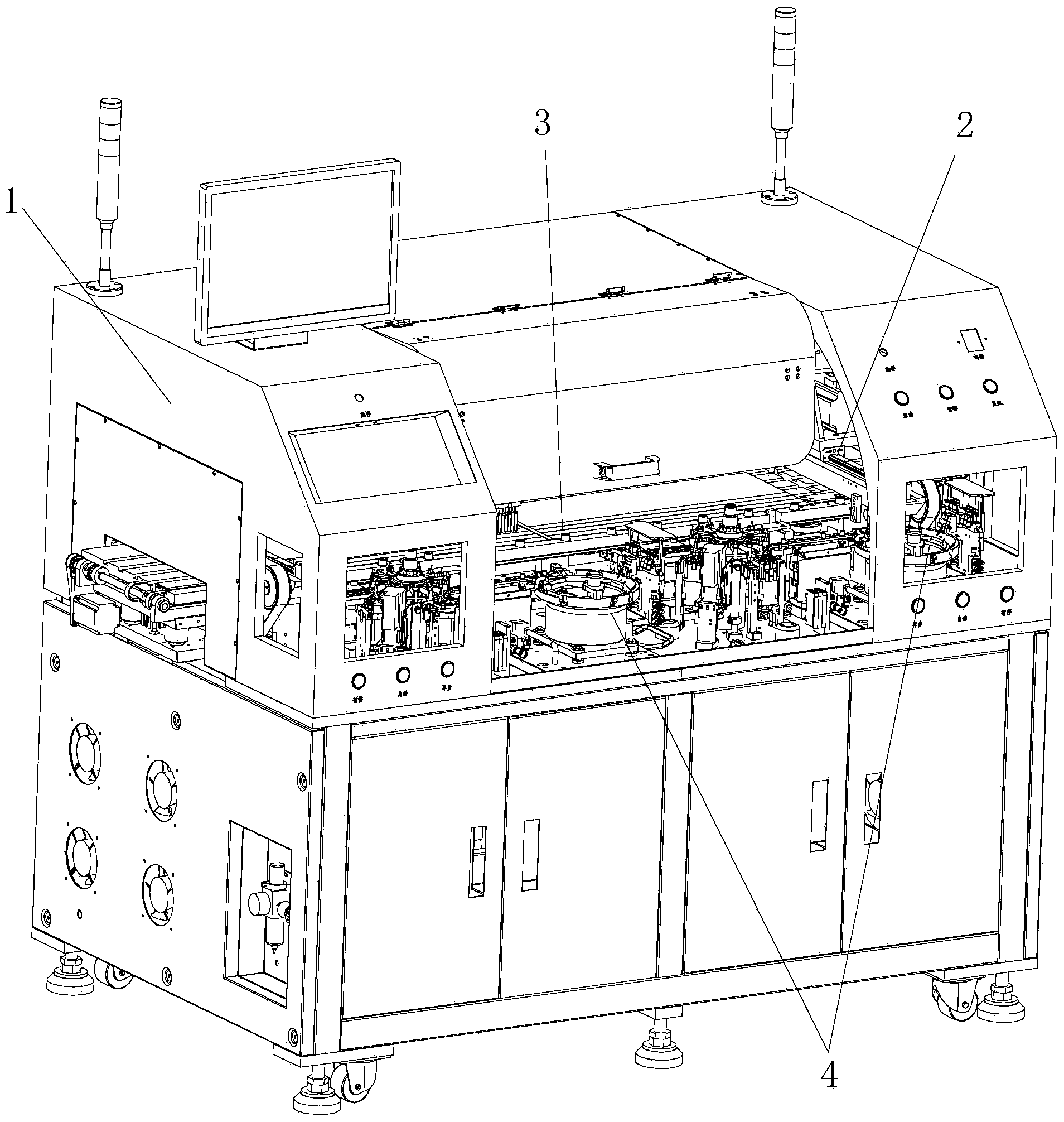
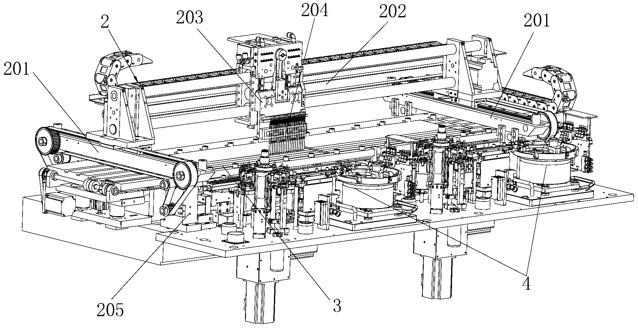
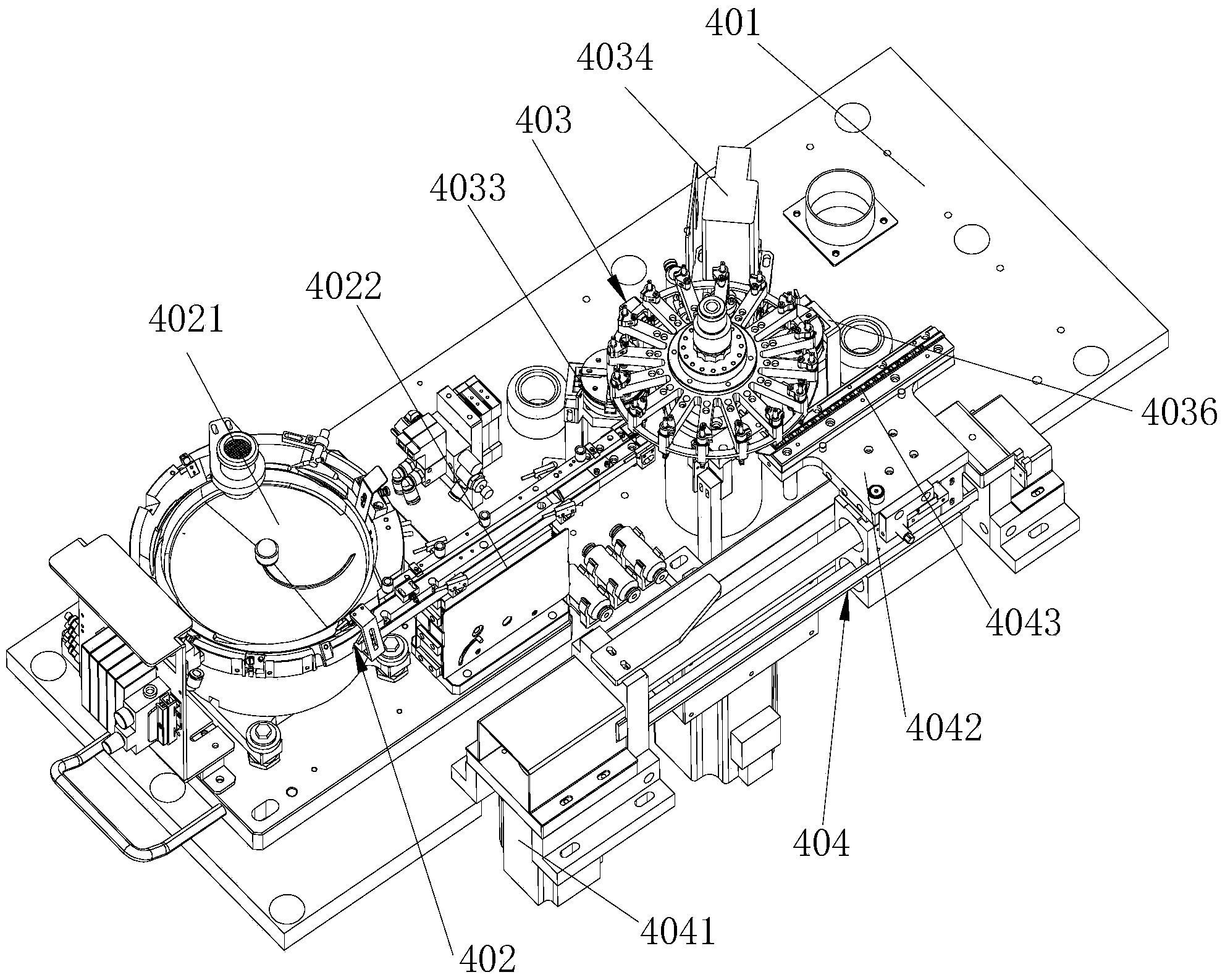
[0046] Such as Figure 1 to Figure 7 The shown LED placement machine includes a body 1, a placement device 2, a lamp board device 3 and at least one set of feeding devices 4, the lamp board device 3 is installed on the rear side of the cabinet 1, and the lamp The two ends of the panel device 3 protrude from the left and right ends of the chassis 1, and the lamp panel device 3 is connected to the patch device 2; the patch device 2 is installed in the chassis 1 and is located above the lamp panel device 3 The feeding device 4 includes a base plate 401, a vibrating plate assembly 402, an indexing plate assembly 403 and a feeding assembly 404, the base plate 401 is installed on the front side in the cabinet 1, the vibrating plate assembly 402, the indexing plate The component 403 and the feeding component 404 are all installed on the bottom plate 401, and the vibrating pla...


PUM


Abstract

The invention discloses an LED chip mounter which comprises a chip mounter body, a chip mounting device, a lamp panel device and at least one feeding device. The lamp panel device is installed on the rear side of the inside of a case, the two ends of the lamp panel device extend out of the left end and the right end of the chip mounter body, the lamp panel device is connected with the chip mounting device, and the chip mounting device is installed in the chip mounter body and is located above the lamp panel device. The feeding device and the lamp panel device are improved, the mode of increasing the feeding speed is combined with the mode of reducing manufacturing procedures, production cost is reduced, labor intensity of operators is reduced, and work efficiency is greatly improved. Accordingly, when feeding is carried out, the positions of LED lamp beads are accurate, an LED lamp panel on the lamp panel device is not prone to deforming, good planeness is achieved and chip mounting quality of the chip mounter is improved.

Description

technical field [0001] The invention relates to LED placement machine equipment, in particular to an LED placement machine. Background technique [0002] LED placement machine is the main equipment for producing LED. The current LED placement machine mainly includes three parts: feeding device, lamp panel device and placement device. When working, the SMT device grabs the LED lamp beads from the feeding device, and then places the captured LED lamp beads on the light board in the light board device for mounting operation, thus completing the LED SMT process. Although the traditional LED placement machine can complete the LED placement process, it still has the following technical defects: 1. In order to ensure the placement quality, this results in low placement efficiency; 2. The placement device absorbs LED lights from the feeding device When the LED lamp beads are placed in the feeding device, there is uncertainty, resulting in low precision of the placement of the LED ...

Claims


Application Information

Patent Timeline
Patent Type & Authority Applications(China)
IPC IPC(8): H05K3/30
CPCH05K3/303H05K2201/10106
Inventor 邓朝旭
Owner 深圳市朝阳光科技有限公司
Learn More