Automatic rolling die

A rolling die, automatic technology, applied in metal processing equipment, forming tools, manufacturing tools, etc., can solve the problems of high cost, increase production cost, large volume, etc., and achieve the effect of low cost and simple structure

Active Publication Date: 2017-05-24
LIUZHOU LIUHE FANGSHENG MACHINERY
View PDF4 Cites 2 Cited by
  • Summary
  • Abstract
  • Description
  • Claims
  • Application Information

AI Technical Summary

Problems solved by technology

[0002] In the machining and manufacturing industry, rolling parts are often encountered. Most of the rolling machines currently on the market are large in size and are only suitable for processing large-scale rolling parts. For small thin-plate cylindrical parts The processing is not only costly, but also takes a lot of time to set up and correct, and the efficiency is low
Moreover, the rolling molds of these rolling machines have complex structures, and generally need to be moved from the side by a cylinder or a wedge to complete the rolling, which also increases the production cost.

Method used


Image

  • Automatic rolling die
  • Automatic rolling die
  • Automatic rolling die

Examples


Embodiment 1

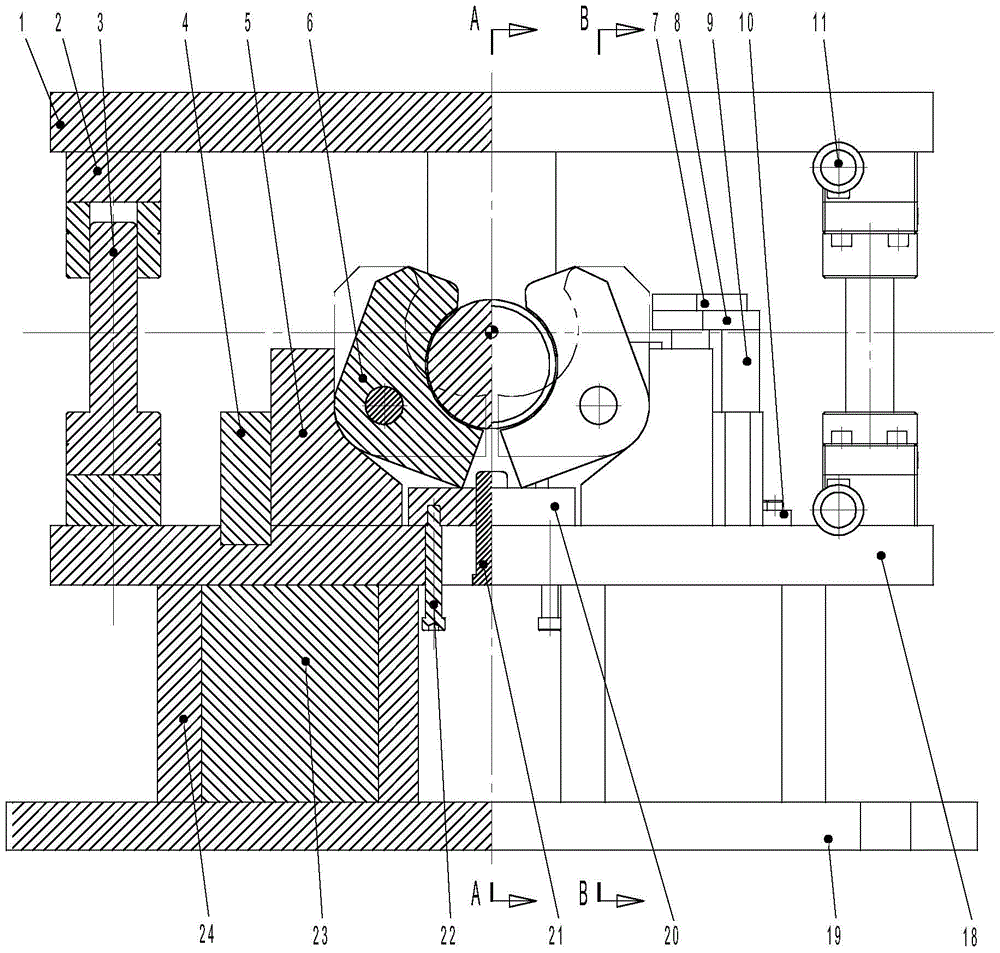
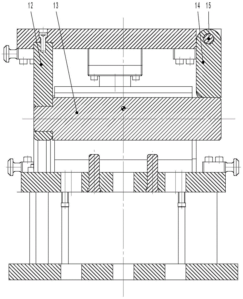
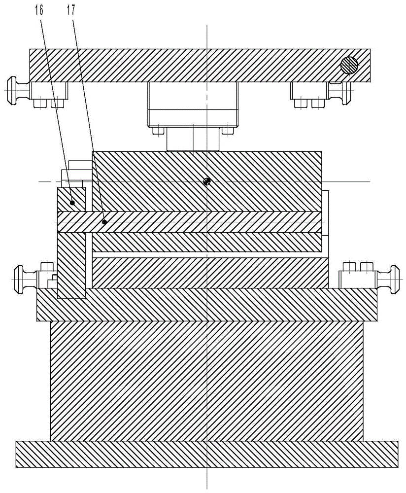
[0028] A kind of automatic rolling round mold, comprises upper template 1, punch 13, die 6, lower mold fixing plate 18 and lower bottom plate 19, described punch 13 one end is connected with the bottom of upper template 1 through punch fixing plate 12 , the top of the other end is provided with a punch support plate 14, the top of the punch support plate 14 is connected to the upper template 1 through the upper mold fixing pin 15; the die 6 is composed of two symmetrical L-shaped concave modules on the left and right The inner side of the two L-shaped concave modules is provided with an inner arc that can surround the punch 13, and the corner of each L-shaped concave module is provided with a lower mold fixing pin 17, and one end of the lower mold fixing pin 17 passes through the Lower die fixed pin fixed plate 16 is installed on the lower mold fixed plate 18; said die 6 both sides are also provided with die fixed seat 5, and this die fixed seat 5 is fixed on the lower mold fix...


PUM


Abstract

The invention relates to a mechanical machining die, in particular to an automatic edge rolling die. The automatic edge rolling die comprises an upper die plate, a male die body, a female die body, a lower die fixing plate and a lower base plate. The male die body is connected with the upper die plate through a male die fixing plate and a male die supporting plate. The female die body is composed of a left L-shaped female die block and a right L-shaped female die block, wherein the left L-shaped female die block and the right L-shaped female die block are symmetrical. The inner sides of the two L-shaped female die blocks are provided with inner circular arcs which can surround the male die body. Each L-shaped female die block is installed on the lower die fixing plate through a lower die fixing pin and a lower die fixing pin fixing plate. Female die fixing bases are further arranged on the two sides of the female die body. Each female die fixing base is fixed to the lower die fixing plate. Female die pressing and supporting assemblies fixed to the lower die fixing plate are installed on the two sides of each female die fixing base. The bottom of the lower die fixing plate is connected with the lower base plate through lower plate supporting blocks. The top of the lower die fixing plate is connected with the upper die plate through guide post guide sleeves. A material returning plate is further installed on the lower die fixing plate. The automatic edge rolling die is simple in structure, low in cost, high in production efficiency and suitable for machining and producing small-sized sheet type cylinder parts.

Description

technical field [0001] The invention relates to a mechanical processing mold, in particular to an automatic rolling round mold. Background technique [0002] In the machining and manufacturing industry, rolling parts are often encountered. Most of the rolling machines currently on the market are large in size and are only suitable for processing large-scale rolling parts. For small thin-plate cylindrical parts The processing is not only costly, but also takes a lot of time for clamping and calibration, and the efficiency is low. Moreover, the rolling dies of these round rolling machines have complex structures, and generally all need to move from the side through the cylinder or the inclined wedge to complete the rolling, which also increases the production cost. Contents of the invention [0003] The technical problem to be solved by the present invention is to provide an automatic rolling die with simple structure, low cost and high efficiency, which is suitable for the...

Claims


Application Information

Patent Timeline
Patent Type & Authority Patents(China)
IPC IPC(8): B21D37/10B21D5/06
CPCB21D5/06B21D37/10
Inventor 文建稳
Owner LIUZHOU LIUHE FANGSHENG MACHINERY
Why Eureka
Try Eureka