A fixture for valve end face processing

An end face processing and fixture technology, applied in the direction of manufacturing tools, metal processing equipment, metal processing machinery parts, etc., can solve the problems of increasing the work intensity of employees, unable to effectively fix the valve, reducing production efficiency, etc., to improve clamping instability, The effect of good self-locking and improving clamping efficiency

Active Publication Date: 2017-01-25
FUZHOU YINSHENGWANG SANITARY WARE
View PDF1 Cites 0 Cited by
  • Summary
  • Abstract
  • Description
  • Claims
  • Application Information

AI Technical Summary

Problems solved by technology

[0004] However, fixing the bolt holes and pattern holes on the flange one by one not only wastes time, increases the work intensity of employees, and reduces production efficiency, but also because the flange will generate a large torque during processing, which will easily make the valve tilt. The one-sided fixing method cannot effectively fix the valve

Method used


Image

  • A fixture for valve end face processing
  • A fixture for valve end face processing
  • A fixture for valve end face processing

Examples


Embodiment Construction

[0019] In order to make the technical means, creative features, goals and effects achieved by the present invention easy to understand, the present invention will be further described below in conjunction with specific illustrations.

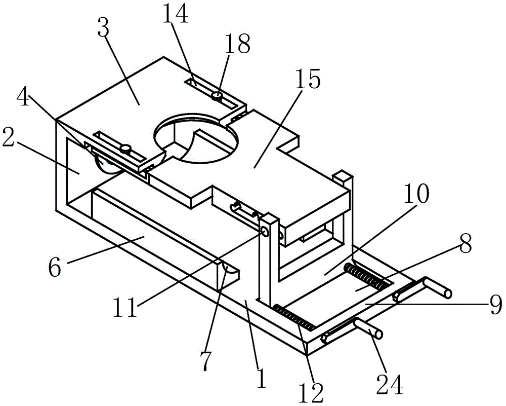
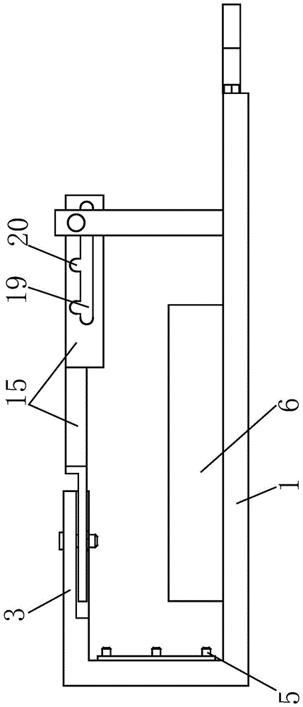
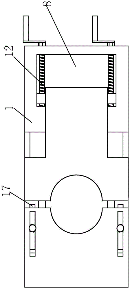
[0020] like Figure 1 to Figure 6 As shown, a fixture for valve end face processing includes a base plate 1, a left plate 2 is provided on the left side of the base plate 1, and a left pressing plate 3 parallel to the base plate 1 is provided on the right side of the upper part of the left plate 2. The inner side of the left side plate 2 is fixed with a positioning plate 4 by bolts, and the positioning plate 4 is provided with at least two positioning pins 5 that cooperate with the bolt holes on the flange at the end of the valve, so that the flange is fixed on the valve. On the positioning plate 4, the front and rear sides of the base plate 1 are respectively provided with a stopper 6, and the upper inner side of the stopper 6 is provided with ...


PUM


Abstract

The invention relates to a clamp for processing the end face of a valve. The clamp comprises a base plate, wherein a left side plate is arranged on the left side of the base plate; a left pressing plate parallel to the base plate is arranged on the right side of the upper part of the left side plate; a positioning plate is fixed on the inner side surface of the left side plate through a bolt; at least two positioning pin columns are arranged on the positioning plate; a slideway is formed on the upper end face of the right part of the base plate; a stop column is arranged at the right end of the base plate; a right side plate is arranged in the slideway; a transverse shaft is arranged at the upper part of the right side plate; a threaded rod is arranged on each of the front side and the back side of the stop column; a concave opening I is formed in the right end of the left pressing plate; a strip-type hole I is formed in each of the front side and the back side of the left pressing plate; a right pressing plate sleeves the transverse shaft; a concave opening II is formed in the middle of the left side of the right pressing plate; a strip-type hole II matched with each strip-type hole I is formed in each of the front side and the back side of the left part of the right pressing plate. By the adoption of the replaceable positioning plate, the positioning pin columns on the positioning plate are used for fixing bolt holes in the valve; different types of valves can be positioned by replacing the positioning plate; the clamp disclosed by the invention is wide in application range and is flexible for assembling and clamping.

Description

technical field [0001] The invention relates to the technical field of grinding equipment, in particular to a clamp for valve end face processing. Background technique [0002] Flanges are commonly used for pipeline connections. In order to ensure the tightness of pipeline connections, when making flanges, there are high requirements for the roundness and flatness of the flange end faces, especially for the position of the bolt holes on the flanges. In order to ensure the processing accuracy of the flange and the bolt holes on the flange, people need a fixture that can accurately locate and firmly clamp the flange. [0003] The patent with the application number ZL201120187493.6 discloses a special fixture for valve body flange drilling, which includes a cross bar pressed on the lower part of the water inlet of the valve body, and a support frame is installed on both ends of the cross bar, and the support frame is fixed A mold plate matching the size of the end face of the ...

Claims


Application Information

Patent Timeline
Patent Type & Authority Patents(China)
IPC IPC(8): B23Q3/06B24B41/06
CPCB23Q3/062B24B41/06
Inventor 鲁明鲁传玉鲁俊
Owner FUZHOU YINSHENGWANG SANITARY WARE
Why Eureka
Try Eureka