Stator core components and stator, permanent magnet motor

A technology for stator cores and components, which is applied to electric components, magnetic circuits, electrical components, etc., can solve the problems of high operating noise and poor magnetization effect of permanent magnet motors, so as to reduce operating noise, improve magnetization effect, optimize effect of structure

Active Publication Date: 2018-03-23
GUANGDONG WELLING ELECTRIC MACHINE MFG +1
View PDF4 Cites 0 Cited by
  • Summary
  • Abstract
  • Description
  • Claims
  • Application Information

AI Technical Summary

Problems solved by technology

[0003] The purpose of the present invention is to overcome the deficiencies of the above-mentioned prior art, and provide a stator core assembly, a stator, and a permanent magnet motor, which solve the technical problems of poor magnetization effect and high operating noise of the existing permanent magnet motor

Method used


Image

  • Stator core components and stator, permanent magnet motor
  • Stator core components and stator, permanent magnet motor
  • Stator core components and stator, permanent magnet motor

Examples


Embodiment 1

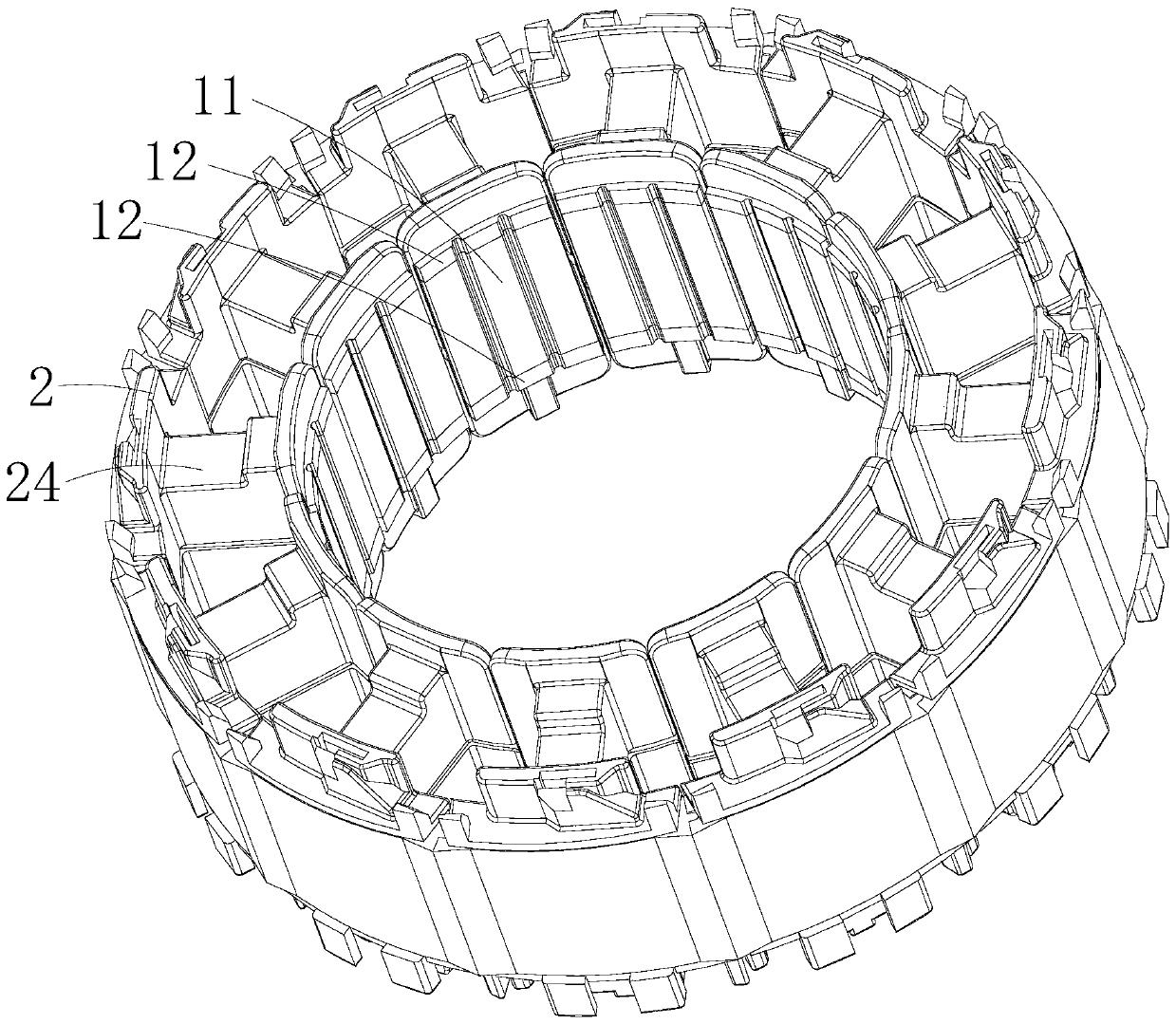
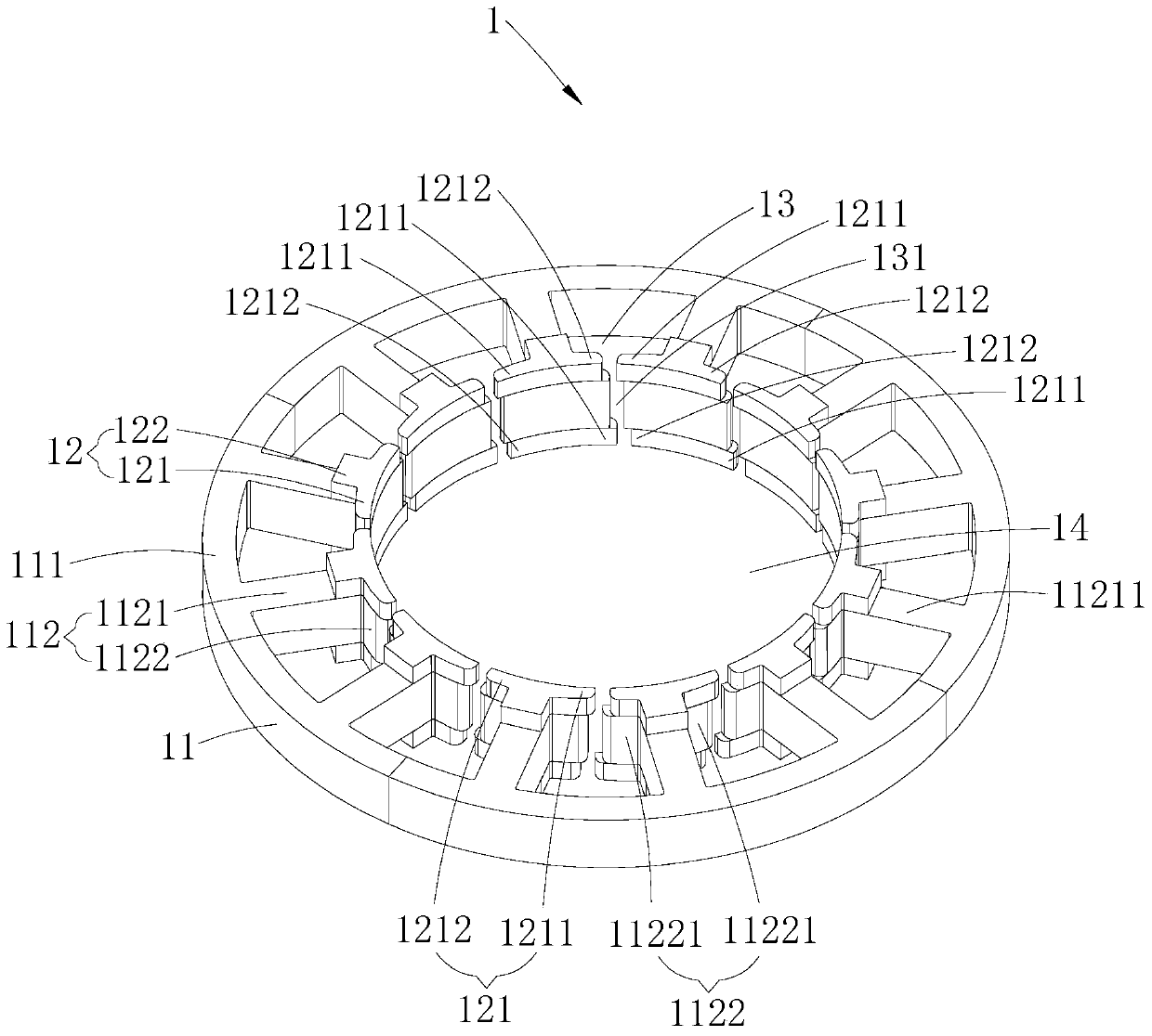
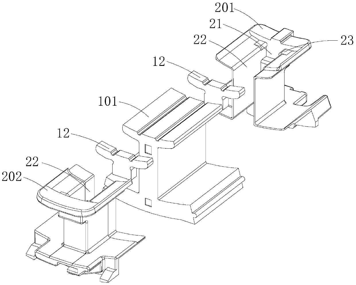
[0029] Such as Figure 1~3 As shown, the stator core assembly provided by Embodiment 1 of the present invention includes a stator core 1. The stator core 1 includes a core body 11 and several magnetically conductive bosses 12. The iron core body 11 includes a stator yoke 111 and several For the stator teeth 112 arranged on the stator yoke 111, at least one stator tooth 112 is laminated with a magnetic conduction boss 12 along the axial direction of the stator core 1 on the end of the stator tooth 112 away from the stator yoke 111, and a magnetic conduction boss 12 is laminated thereon. The stator teeth 112 of the platform 12, the stator teeth 112 adjacent to the stator teeth 112, and the magnetically conductive bosses 12 superimposed on the two stator teeth 112 surround and form a notch 131 in the circumferential direction, which is an oblique notch. The winding slot 13 , the notch 131 of the winding slot 13 is located at the end of the winding slot 13 away from the stator yok...

Embodiment 2

[0049] In the stator core assembly, the stator and the permanent magnet motor provided by Embodiment 2 of the present invention, the magnetically conductive boss 12 is laminated only on one axial side of the stator tooth 112 . And preferably, the quantity of the magnetic conduction boss 12 is the same as the number of the stator teeth 112, each stator tooth 112 is provided with a magnetic conduction boss 12, and each magnetic conduction boss 12 is arranged along the axial direction of the stator core 1 on the same side of each stator tooth 112 . The main difference between the present embodiment and the first embodiment is: in the first embodiment, the stator teeth 112 are laminated with magnetically conductive bosses 12 on both axial sides, so that the axial length of the stator core 1 is toward the The both sides of iron core body 11 lengthen, and the inclination effect of inclined notch opening is good; And in the present embodiment, only on the axial side of stator tooth 1...

Embodiment 3

[0051] In the stator core assembly, the stator and the permanent magnet motor provided by the third embodiment of the present invention, the number of magnetically conductive bosses 12 is less than twice the number of stator teeth 112, and the two adjacently arranged guides along the circumferential direction of the stator core 1 At least one stator tooth 112 is spaced between the magnetic bosses 12 . Specifically, each magnetically conductive boss 12 is laminated on each stator tooth 112 in the form of at least one stator tooth 112 along the circumferential direction of the stator core 1 , so that not every stator tooth 112 is laminated with a magnetically conductive The boss 12 can also play the role of lengthening the axial length of the stator core 1 and forming the oblique slot opening, thereby also achieving the purpose of improving the magnetization effect of the permanent magnet motor and reducing the harmonics of the permanent magnet motor. The difference between the ...


PUM


Abstract

The invention discloses a stator iron core component, a stator and a permanent magnet motor, which are suitable for the motor field. The stator iron core component comprises a stator iron core, wherein the stator iron core comprises a stator yoke, and a plurality of stator teeth which are formed in the stator yoke; the end part, far away from the stator yoke, of at least one stator tooth is overlapped with a magnetic conductive convex platform along the axial direction of the stator iron core; one winding groove, of which a groove opening is an inclined groove opening, is formed by encircling one stator tooth overlapped with the magnetic conductive convex platform, another stator tooth adjacent to the stator tooth, and the magnetic conductive convex platform overlapped between the two stator teeth in the circumferential direction. According to the stator iron core component, the stator and the permanent magnet motor, the axial length of the stator iron core is lengthened by utilization of the magnetic conductive convex platforms, the magnetic accumulation effect of the permanent magnet motor is improved, the turn length of a stator winding is reduced, the weight of the stator winding is reduced, the weight of the stator iron core is reduced, and the axial length of the permanent magnet motor is reduced; meanwhile, the groove opening of the winding groove is one inclined groove opening through the magnetic conductive convex platform, so that the harmonic wave of the permanent magnet motor can be reduced, and then the torque fluctuation and noises in the running process of the permanent magnet motor are reduced.

Description

technical field [0001] The invention belongs to the field of motors, in particular to a stator core assembly, a stator with the stator core assembly, and a permanent magnet motor with the stator. Background technique [0002] In the prior art, in order to ensure the working performance (power, torque, etc.) of the permanent magnet motor, the axial length of the rotor of the permanent magnet motor is generally set to be greater than the axial length of the stator core. Although the existing permanent magnet motors meet the design requirements for the performance of permanent magnet motors, there are still deficiencies in specific applications, which are specifically reflected in; due to the distance between the axial end face of the rotor and the axial end face of the stator core Therefore, the magnetic flux collected from the permanent magnet of the rotor to the stator core is less, so that the magnetic flux gathering effect of the permanent magnet motor is poor; and when th...

Claims


Application Information

Patent Timeline
Patent Type & Authority Patents(China)
IPC IPC(8): H02K1/14H02K1/16
CPCH02K1/146H02K1/165H02K29/03
Inventor 王飞朱婷婷朱嘉东陈金涛
Owner GUANGDONG WELLING ELECTRIC MACHINE MFG
Why Eureka
Try Eureka