Power part structure of cogging mill

A blanking machine and power technology, which is applied to the structural field of the power part of the blanking machine, can solve the problems of damage to the herringbone gear set of the power reducer, inconvenient installation and connection, affecting the transmission stability, etc., to achieve a fast and smooth connection effect and improve assembly. Convenience, quick and smooth assembly

Active Publication Date: 2015-01-21
CHONGQING IRON & STEEL CO LTD
View PDF7 Cites 3 Cited by
  • Summary
  • Abstract
  • Description
  • Claims
  • Application Information

AI Technical Summary

Problems solved by technology

[0004] Among them, in the existing structure of the power part, the coupling used is a structure in which the ends of the two connecting shafts are connected by flanges. This structure has the following defects: 1: Since the billet needs to be processed by the billet Rolling for the first time, the work load is very large, and the power transmission torque is relatively large, resulting in the output shaft of the power reducer and the input shaft of the docked herringbone gear seat in the structure of the power part are all shafts with large diameters, so the shaft end flange It is difficult to align the connecting holes, which makes it very inconvenient and time-consuming to install and connect; 2. Due to the very large vibration of the blanking machine during operation, the reaming bolts used for connection and the walls of the connecting holes will be damaged under long-term vibration of the coupling. Wear and friction, resulting in loosening of the gap, affecting the transmission stability and generating vibration noise. After the vibration increases, it will even damage the power reducer and the herringbone gear set, resulting in shutdown for maintenance

Method used


Image

  • Power part structure of cogging mill
  • Power part structure of cogging mill
  • Power part structure of cogging mill

Examples


specific Embodiment approach

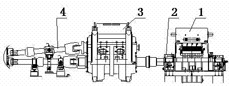
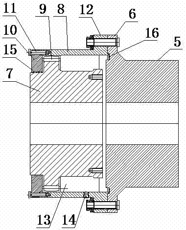
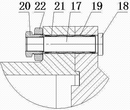
[0022] Specific implementation methods: such as Figure 1-Figure 3 As shown, a power part structure of a blanking machine includes a power motor 1, the output end of the power motor 1 is connected to the power reducer 2 and then connected to a herringbone gear seat 3 through a coupling, and the two herringbone gear seats 3 The output end is connected to the ends of the lower roll and the upper roll through the composite joint shaft 4 and drives the lower roll and the upper roll to rotate respectively; wherein, the coupling includes a ring formed by protruding from the end of the output shaft 5 of the power reducer along the circumferential direction. A circle of flange flange 6; It also includes a connecting sleeve 8 sleeved on the end of the input shaft 7 of the herringbone gear seat. The outer ring gear 9 set on a circle of raised surface meshes, the end of the connecting sleeve 8 close to the herringbone gear seat is fixed with a screw 11 along the axial direction, and a li...


PUM


Abstract

The invention discloses a power part structure of a cogging mill. The power part structure comprises a power motor, the output end of the power motor is connected with a power reducer and then is connected with a herringbone gear seat through a coupler, and the two output ends of the herringbone gear seat are connected with the end of a lower roll and the end of an upper roll through composite connecting shafts. The power part structure is characterized in that the end of an input shaft of the herringbone gear seat is connected and provided with a limiting sleeve and a connecting sleeve, the connecting sleeve and the input shaft of the herringbone gear seat are in transmission fit through gear meshing, and the connecting sleeve is fixedly connected with an output shaft of the power reducer through a flange and a flange protrusion arranged between the connecting sleeve and the output shaft of the power reducer and a reaming bolt. According to the power part structure of the cogging mill, mounting and butt joint of the output shaft of the power reducer and the input shaft of the herringbone gear seat can be facilitated, and assembling convenience is improved; meanwhile, the clearance of a connecting bolt and connecting holes in a coupler can be adjusted and eliminated conveniently, transmission reliability and stability are guaranteed, and the smooth work of the power part is guaranteed.

Description

technical field [0001] The invention relates to a blanking machine used in steelmaking equipment; in particular, it relates to a structure of the power part of the blanking machine. Background technique [0002] The blanking machine is the equipment connected to the exit of the heating furnace in the steelmaking equipment, which is used to shape the billet of the rolled piece coming out of the heating furnace and remove the oxide scale on the surface of the billet, which can roll the billet into the required shape , size, structure and performance, so that the rolling mill can bite into it. [0003] The billet opening machine structure generally includes a frame, a lower roll fixedly installed on the frame and an upper roll horizontally arranged above the lower roll. The upper end of the upper roll is provided with a pressing mechanism. The output end of the pressing motor is connected to the pressing reducer, and the pressing reducer has an output shaft arranged in paralle...

Claims


Application Information

Patent Timeline
Patent Type & Authority Applications(China)
IPC IPC(8): F16D1/033B21B35/12B21B45/04B21D1/02B21D3/02
Inventor 李兴杰李海兵高林
Owner CHONGQING IRON & STEEL CO LTD
Why Eureka
Try Eureka