Torsional damper

A torsional vibration damper and device technology, applied in the field of torsional vibration dampers

Active Publication Date: 2015-01-21
SCHAEFFLER TECH AG & CO KG
View PDF5 Cites 6 Cited by
  • Summary
  • Abstract
  • Description
  • Claims
  • Application Information

AI Technical Summary

Problems solved by technology

But the centrifugal pendulum has the disadvantage that it only works for a certain frequency spectrum

Method used


Image

  • Torsional damper
  • Torsional damper

Examples


Embodiment Construction

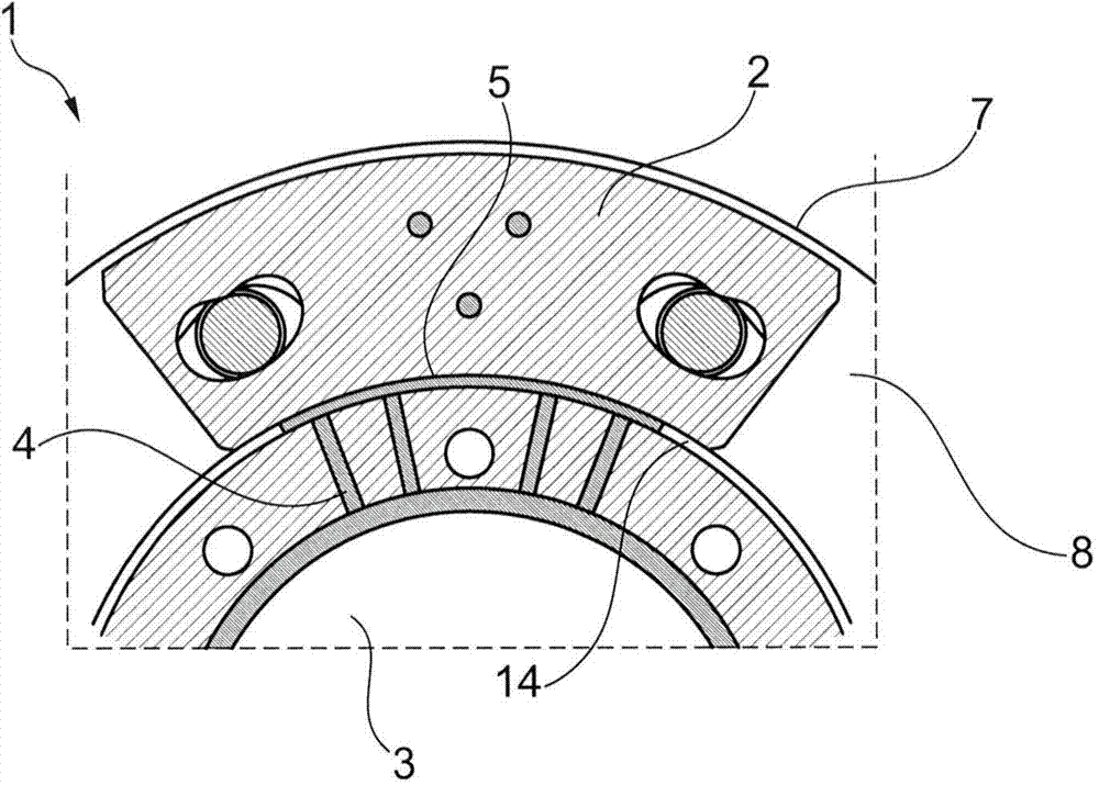
[0039] figure 1 A detail of a torsional vibration damper 1 is shown, wherein a pendulum mass 2 is suspended on a carrier unit 3 . Below the pendulum mass 2 is located a fluid outlet 4 , through which fluid 5 can enter the pressure chamber, thus forming a damping and / or biasing means 8 . The pendulum mass 2 forms a centrifugal pendulum 7 on the carrier unit 3 . The incoming liquid 5 primarily acts on the inner side 14 of the pendulum mass 2 and thus produces a pressure drop across the pendulum mass 2 .

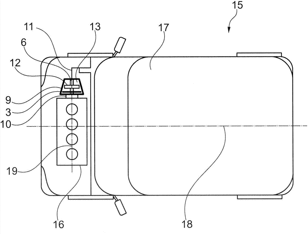
[0040] exist figure 2 A motor vehicle 15 is shown in , which has a drive unit 16 in front of its driver's cab 17 , whose engine axis 19 is transverse to the longitudinal axis 18 of the motor vehicle 15 , which is here schematically represented as an internal combustion engine. The drive unit 16 is detachably connectable via its output shaft 10 by means of a friction clutch 9 to a purely schematically indicated drive train 11 . For this purpose, a disk pack 12 is provided i...


PUM


Abstract

The invention relates to a torsional damper used for a rotary bearer having a rotary center; the torsional damper at least comprises the following parts: a centrifugal force swing; a damper and / or a bias device matched for affecting a fixed frequency of the centrifugal force swing, wherein the damper and / or bias device is applied to at least one swing mass of the swing masses; the torsional damper can use simple measurement to compensate different frequency of the locomotive, and especially aims to the low starting frequency and high frequency in driving.

Description

technical field [0001] The invention relates to a torsional vibration damper for a rotatable carrier unit with a center of rotation, in particular for a friction clutch, a torque armature or a dual-mass oscillator. Background technique [0002] Engines are used in modern motor vehicles, which are increasingly running at low speeds. It is precisely at such low rotational speeds that natural frequencies of components in the drive train or in the body of the motor vehicle are encountered. This low frequency must therefore be compensated exactly. For this purpose, it is known, for example, to use centrifugal pendulums, wherein a high mass must be used for damping low frequencies. A disadvantage of this is that a high mass inertia reduces the efficiency of the torque transmission. Furthermore, the structural size and / or the production costs of such a centrifugal force pendulum necessarily increase with an increase in mass. In addition, exceptionally low natural frequencies ca...

Claims


Application Information

Patent Timeline
Patent Type & Authority Applications(China)
IPC IPC(8): F16F15/16F16F15/14F16F15/131
Inventor L·伊艾兴A·特里勒
Owner SCHAEFFLER TECH AG & CO KG
Why Eureka
Try Eureka