
System and method for magnetometer calibration and compensation

A magnetometer, a technology for calibrating parameters, applied in the size/direction of the magnetic field, electric magnetometer, measuring magnetic variables, etc., and can solve problems such as deformation

Inactive Publication Date: 2015-01-21
HONEYWELL INT INC
View PDF4 Cites 33 Cited by
  • Summary
  • Abstract
  • Description
  • Claims
  • Application Information

AI Technical Summary

Problems solved by technology

However, magnetometer measurements can be distorted by various types of magnetic disturbances in the vicinity of the magnetometer

Method used


Image

  • System and method for magnetometer calibration and compensation
  • System and method for magnetometer calibration and compensation
  • System and method for magnetometer calibration and compensation

Examples


example 1

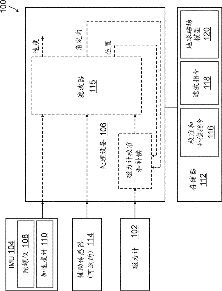
[0110] Example 1 includes a system comprising: an inertial measurement unit including one or more gyroscopes configured to measure angular velocity about respective ones of three independent axes, and configured to measure angular velocity along three independent axes one or more accelerometers of the specific force in the corresponding axis; a magnetometer configured to measure the strength of the local magnetic field along each of the three independent axes; and a processing device coupled to the inertial measurement unit and the magnetic force the processing device is configured to calculate motion state data of the system based on measurements received from the magnetometer and the inertial measurement unit; wherein the processing device is further configured to calculate a magnetometer measurement calibration parameter using a first technique when the position data is unavailable, And when position data is available, magnetometer measurement calibration parameters are calc...

example 2

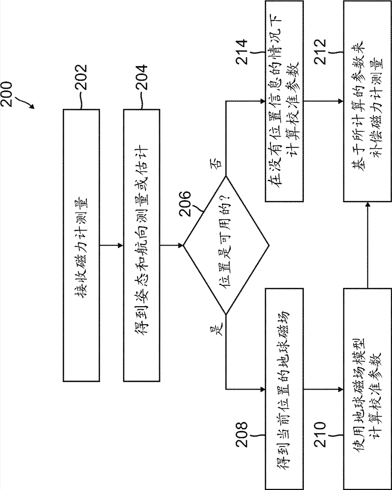
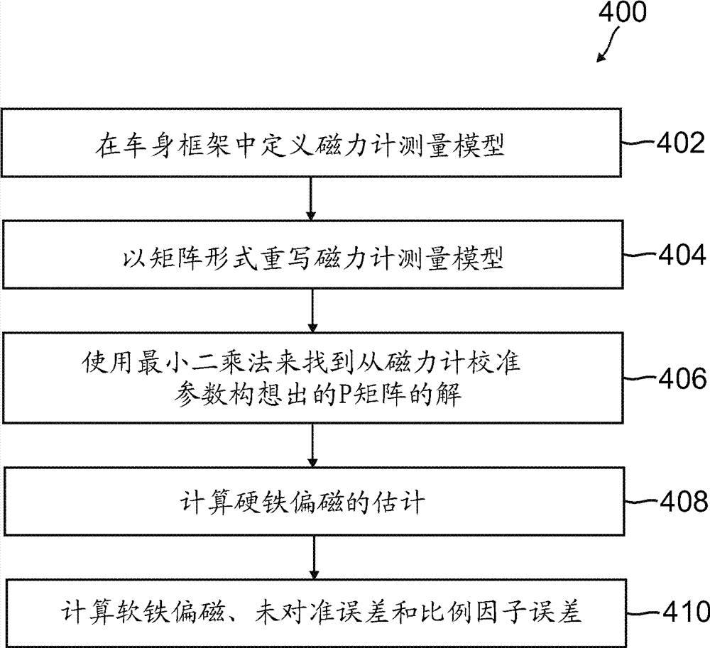
[0111] Example 2 includes the system of example 1, wherein to calculate the magnetometer measurement calibration parameters when the position data is unavailable, the processing device is configured to: calculate the hard iron bias vector from a matrix factorization of a matrix containing entries based on the magnetometer measurements ; and calculating at least one of a soft iron bias matrix, a scale factor error matrix, and a misalignment error matrix using the magnetometer measurements and the hard iron bias vector.

example 3

[0112] Example 3 includes the system of example 1, wherein to calculate the magnetometer measurement calibration parameters when the location data is available, the processing device is configured to: determine a column of a matrix containing estimated magnetic field values ​​derived from an Earth Magnetic Field Map (EMFM) based on the location data If the matrix has a full column, calculate all the magnetometer measurement calibration parameters of the magnetometer measurement model; and if the matrix does not have a full column, calculate a subset of the magnetometer measurement calibration parameters.


PUM


Abstract

A system comprises an inertial measurement unit comprising one or more gyroscopes configured to measure angular velocity about a respective one of three independent axes and one or more accelerometers configured to measure specific force along a respective one of the three independent axes; a magnetometer configured to measure strength of a local magnetic field along each of the three independent axes; and a processing device coupled to the inertial measurement unit and the magnetometer; the processing device configured to compute kinematic state data for the system based on measurements received from the magnetometer and the inertial measurement unit. The processing device is further configured to calculate magnetometer measurement calibration parameters using a first technique when position data is unavailable and to calculate magnetometer measurement calibration parameters using a second technique when position data is available.

Description

technical field [0001] The present invention relates to systems and methods for magnetometer calibration and compensation. Background technique [0002] A magnetic compass can be used to determine the vehicle's heading angle or as part of a vector matching algorithm to determine the vehicle's attitude (roll and pitch) and heading angles. A three-axis magnetometer, which measures all three components of the Earth's magnetic field, can still be used to determine the vehicle's heading angle even if the vehicle is tilted by some value of pitch and roll angles. However, the measurements of a magnetometer can be distorted by various types of magnetic disturbances in the vicinity of the magnetometer. Some types of magnetic perturbations, such as ferromagnetic materials, are known as "hard iron" biases and can add to the magnetic field measured by a magnetometer. Other types of magnetic perturbations, known as "soft iron" biases, can change the magnitude and direction of the magne...

Claims


Application Information

Patent Timeline
IPC IPC(8): G01C25/00
CPCG01R35/005G01R33/0035G01R33/028G01R33/02G01C21/1654G01C17/38
Inventor M.R.埃尔格斯马V.L.贝奇什瓦R.D.克雷肖夫
Owner HONEYWELL INT INC
Learn More