Low-reflection and neutral-density filter
A neutral density, low reflection technology, applied in the direction of filters, optics, optical components, etc., can solve the problems of color cast, inability to meet the requirements of instruments and equipment, poor neutrality, etc., to achieve the effect of taking into account the performance.
Active Publication Date: 2015-01-21
SHENYANG ACAD OF INSTR SCI
View PDF4 Cites 9 Cited by
- Summary
- Abstract
- Description
- Claims
- Application Information
AI Technical Summary
Problems solved by technology
[0004] At present, there is a low-reflection neutral density filter on the market, but it is based on a resin sheet and obtained through a chemical reaction. Good (color cast) and other shortcomings, unable to meet the needs of high-end instruments and equipment
Method used
View moreImage
Smart ImageViewing Examples
Examples
example 1
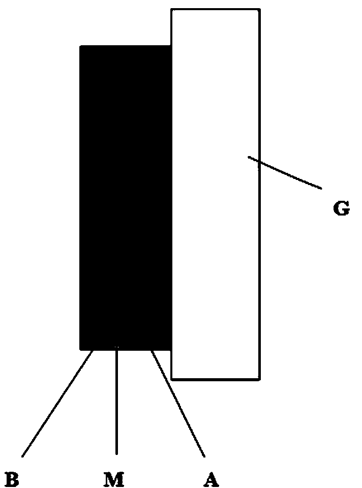
[0039] Example 1: Single-sided coating structure
[0040] Substrate: B270 glass
[0041] Dielectric material: TiO 2 , SiO 2
[0042] Metal material: Ni-Cr.
[0043] The following film system is plated on one side of the substrate.
[0044]
Login to View More PUM
 Abstract
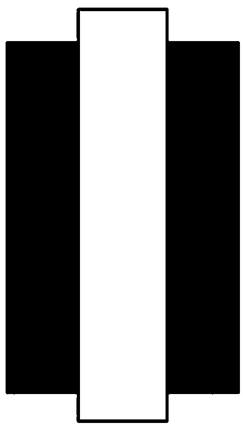
The invention belongs to the field of optical elements for optical energy attenuation, and particularly relates to a low-reflection and neutral-density filter. The low-reflection and neutral-density filter comprises a substrate and a membrane system layer arranged on the substrate in a plated mode. The membrane system layer is of a G|AMB structure or a BM|G|MB structure, wherein M is a metal layer for achieving transmission attenuation and neutral transmission, G is the substrate, A and B are membrane stacks working cooperatively to achieve wide-spectrum metal antireflection and are each formed by dielectric layers and the metal layers M in an alternately plated mode, the metal layers M are made of Ni-Cr or Ni-Cr-Fe, and the dielectric layers are made of TiO2 or SiO2 or Al2O3 or HfO2 or Ta2O5 or Nb2O5. The low-reflection and neutral-density filter has both low reflection and transmission spectrum neutrality in a wide spectral range.
Description
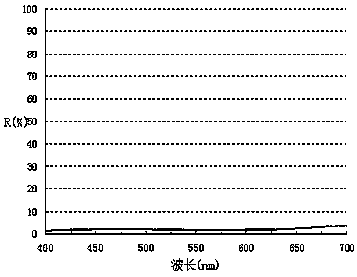
technical field [0001] The invention belongs to the field of light energy attenuation optical elements, in particular to a low-reflection neutral density filter. Background technique [0002] Neutral density filters can uniformly attenuate light in the same proportion in a wide range of wavelengths, and have no selectivity for wavelengths. They are widely used in various instruments and equipment that require attenuation of light energy. The traditional preparation method of the neutral density filter is to coat a solid metal film on the surface of the substrate, and use the light absorption and reflection function of the metal to attenuate the light energy. However, this type of neutral density filter often has a strong reflection effect on light, and the reflectivity is generally above 50%, which makes it unable to be used in the imaging field. [0003] The neutral density filter used in the imaging field has two basic technical requirements: ① Spectral neutrality - the o...
Claims
Login to View More Application Information
Patent Timeline
 IPC IPC(8): G02B5/20G02B1/11
CPCG02B1/115G02B5/205
Inventor 阴晓俊高鹏张勇喜金秀马敬赵珑现
Owner SHENYANG ACAD OF INSTR SCI
Features
- R&D
- Intellectual Property
- Life Sciences
- Materials
- Tech Scout
- Unparalleled Data Quality
- Higher Quality Content
- 60% Fewer Hallucinations
Learn More Browse by: Latest US Patents, China's latest patents, Technical Efficacy Thesaurus, Application Domain, Technology Topic, Popular Technical Reports.
© 2025 PatSnap. All rights reserved.Legal|Privacy policy|Modern Slavery Act Transparency Statement|Sitemap|About US| Contact US: help@patsnap.com


