Accurate visual positioning and orienting method for rotor wing unmanned aerial vehicle

An unmanned and visual positioning technology for rotors, applied in three-dimensional position/channel control and other directions, can solve problems such as difficult implementation, low measurement accuracy, and temperature drift, and achieve the effect of flexibility and convenience, simple calculation, and collision prevention.

Inactive Publication Date: 2015-01-21
NANJING UNIV OF AERONAUTICS & ASTRONAUTICS
View PDF9 Cites 70 Cited by
  • Summary
  • Abstract
  • Description
  • Claims
  • Application Information

AI Technical Summary

Problems solved by technology

The navigation and positioning of traditional rotor UAVs mainly use the combination of IMU (inertial unit) and satellites (such as GPS), which has certain limitations: satellite navigation can only be used outdoors, and is susceptible to interference and drift; IMU is expensive and exists Temperature drift, it is difficult to achieve long-term precise positioning
This method is mainly used for camera position acquisition on a two-dimensional coordinate plane, without dimensional calculation of relative

Method used


Image

  • Accurate visual positioning and orienting method for rotor wing unmanned aerial vehicle
  • Accurate visual positioning and orienting method for rotor wing unmanned aerial vehicle
  • Accurate visual positioning and orienting method for rotor wing unmanned aerial vehicle

Examples


Embodiment 1

[0048] Taking the application of the precise visual positioning and orientation method of the rotor UAV to the power inspection of the small multi-rotor UAV as an example, the working process is as follows:

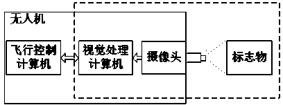
[0049] The small multi-rotor UAV for inspection includes flight control computer, visual processing computer, positioning and orientation camera, frame, propeller, motor and ESC, remote control receiver, battery, micro-single camera for inspection and supporting PTZ, image transmission and other parts. The ground part includes: image transmission receiver, ground station, flight control remote control, camera control and PTZ control remote control. like figure 1 As shown, the UAV is equipped with a camera and a vision processing computer, and the vision processing computer and the flight control computer are connected through a stable bus. The camera lens is pointing straight down.

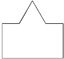
[0050] Selected marker. Since the marker needs to be installed horizontally in this c...

Embodiment 2

[0060] Taking the application of the precise visual positioning and orientation method of the rotor UAV to the insulator detection of the transmission tower of the small multi-rotor UAV as an example, the working process is as follows:

[0061] Insulator detection of transmission towers is an important part of power inspection. High-voltage transmission towers are usually equipped with two-circuit three-phase cables, and insulators are located near the tower for each cable. The method of the present invention can help the unmanned aerial vehicle to detect the multiphase insulators on the same iron tower safely, quickly and autonomously.

[0062] The composition of the small multi-rotor UAV and the devices involved in the precise visual positioning and orientation method of the rotor UAV are basically the same as those in the first embodiment. The only difference is that the camera lens for vision processing is mounted horizontally forward.

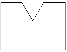
[0063] Selected marker. like F...

Embodiment 3

[0072] Take the application of the precise visual positioning and orientation device and method of the rotary-wing UAV to the building anti-terrorism of the small multi-rotor UAV as an example. The composition of the small multi-rotor UAV used includes: flight control computer, visual processing computer, positioning and orientation camera, frame, propeller, motor and ESC, remote control receiver, battery, monitoring camera, image transmission and other parts. The ground part includes: image transmission receiver, ground station, remote controller for flight control, camera for monitoring and remote controller for PTZ control.

[0073]When a hostage takes place in a window room of a high-rise building, real-time monitoring of the window will be critical. At this time, the fixed-point hovering of the rotary-wing drone, and the real-time aerial photography solution is usually clearer than that of setting up a camera in a nearby building or the ground, and the fixed point is conv...


PUM


Abstract

The invention discloses an accurate visual positioning and orienting method for a rotor wing unmanned aerial vehicle on the basis of an artificial marker. The accurate visual positioning and orienting method includes the following steps that the marker with a special pattern is installed on the surface of an artificial facility or the surface of a natural object; a camera is calibrated; the proportion mapping relation among the actual size of the marker, the relative distance between the marker and the camera and the size, in camera imaging, of the marker is set up, and the keeping distance between the unmanned aerial vehicle and the marker is set; the unmanned aerial vehicle is guided to fly to the position where the unmanned aerial vehicle is to be suspended, the unmanned aerial vehicle is adjusted so that the marker pattern can enter the visual field of the camera, and a visual recognition function is started; a visual processing computer compares the geometrical characteristic of the pattern shot currently and a standard pattern through visual analysis to obtain difference and transmits the difference to a flight control computer to generate a control law so that the unmanned aerial vehicle can be adjusted to eliminate the deviation of the position, the height and the course, and accurate positioning and orienting suspension is achieved. The accurate visual positioning and orienting method is high in independence, good in stability, high in reliability and beneficial for safety operation, nearby the artificial facility the natural object, of the unmanned aerial vehicle.

Description

technical field [0001] The invention belongs to the technical field of cross fusion of unmanned aerial vehicle flight control and computer vision, in particular to a precise visual positioning and orientation method for a rotor unmanned aerial vehicle. Background technique [0002] In recent years, the rotor UAV has been developed rapidly. It has the characteristics of stable flight, easy control, low noise, and low safety hazards. The wider the application. The navigation and positioning of traditional rotor UAVs mainly use the combination of IMU (inertial unit) and satellites (such as GPS), which has certain limitations: satellite navigation can only be used outdoors, and is susceptible to interference and drift; IMU is expensive and exists Temperature drift makes it difficult to achieve long-term precise positioning. In addition, the heading perception of the rotor UAV mainly relies on the magnetic compass. Once it is disturbed, it will seriously affect the hovering and...

Claims


Application Information

Patent Timeline
IPC IPC(8): G05D1/10
Inventor 胡国雄杨忠薛八阳钟山程凯张翔刘相杰
Owner NANJING UNIV OF AERONAUTICS & ASTRONAUTICS
Why Eureka
Try Eureka