
Switching circuit used for switching capacitor and switching control method

A capacitor switching, switching circuit technology, applied in electronic switches, circuits, electrical components and other directions, can solve problems such as arcing

Inactive Publication Date: 2015-01-21
南京诺联配电科技有限公司
View PDF7 Cites 2 Cited by
  • Summary
  • Abstract
  • Description
  • Claims
  • Application Information

AI Technical Summary

Problems solved by technology

[0013] The present invention aims at problems such as inrush current and arcing during the switching process of capacitors, and proposes a switching circuit for switching capacitors and a control method for switching

Method used


Image

  • Switching circuit used for switching capacitor and switching control method
  • Switching circuit used for switching capacitor and switching control method
  • Switching circuit used for switching capacitor and switching control method

Examples


Embodiment Construction

[0024] The content of the present invention is further described below in conjunction with accompanying drawing and embodiment:

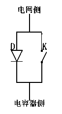
[0025] Such as figure 1 Shown is a schematic diagram of the circuit principle of the switch circuit for capacitor switching in the present invention, which is composed of a unidirectional conduction element D and a controllable switch element K connected in parallel. In this embodiment, the unidirectional conduction element D is a diode. The controllable switching element K is a magnetic latching relay.

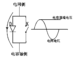
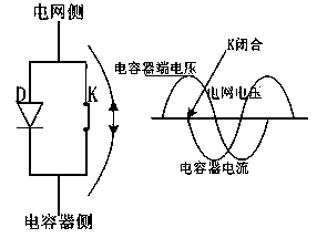
[0026] Such as image 3 Shown is the state of the switching circuit of the capacitor switching in the present invention before it is put into use. At this time, the capacitor is not connected to the power grid. Due to the one-way conduction characteristic of D, the capacitor and the power grid cannot form a complete two-way path at this time, and the voltage peak value is only high on the power grid side. At the capacitor side voltage, the grid c...


PUM


Abstract

The invention provides a novel switching circuit used for switching a capacitor and a switching control method of the capacitor in order to resolve the problems of inrush current, oscillation, arc discharging and restriking of the capacitor in the switching process. The switching circuit is composed of a one-way connection part and a controllable mechanical switch part which are connected in parallel, makes full use of the characteristic that a mechanical switch part is free of loss, and realizes pre-charging of the capacitor through the one-way connection part so that the residual voltage of the capacitor can be the voltage peak value of a power grid. A control switch is input at the peak value of the voltage of the power grid, the switching-on inrush current caused by voltage leap when the capacitor is input is effectively reduced, and the influences of motion response delay of the mechanical switch are eliminated. In combination with the switching control method, no inrush current or arc discharging is generated in the switching process of the capacitor, and a switching loop is free of loss after the capacitor is put into operation.

Description

technical field [0001] The invention relates to the field of power system distribution network automation, in particular to a switching circuit for capacitor switching and a switching control method. Background technique [0002] In the power system, capacitors are widely used in reactive power compensation, voltage adjustment, harmonic suppression and other applications for the power grid, and are one of the important equipment for power system distribution network automation. [0003] When the capacitor is put into the power grid, due to the essential characteristics of the capacitor, it will generate an inrush current when it is put into the power grid. The size of the rated current, such a huge inrush current will have a great impact on the life of the capacitor, cause serious interference to the power grid, and may also damage the switching parts of the capacitor. [0004] When the capacitor is withdrawn from the power grid, since the capacitor has been connected to th...

Claims


Application Information

Patent Timeline
Patent Type & Authority Applications(China)
IPC IPC(8): H03K17/74H03K17/13
Inventor 不公告发明人
Owner 南京诺联配电科技有限公司
Learn More