
Housing structure for an electrical device

A technology for electrical equipment and housings, applied in the field of housing structures

Inactive Publication Date: 2015-01-21
SALCOMP OYJ
View PDF4 Cites 0 Cited by
  • Summary
  • Abstract
  • Description
  • Claims
  • Application Information

AI Technical Summary

Problems solved by technology

If the battery charger is still connected to a wall outlet, there is a potential risk of electric shock from the live terminal prongs

Method used


Image

  • Housing structure for an electrical device
  • Housing structure for an electrical device
  • Housing structure for an electrical device

Examples


Embodiment Construction

[0036] In different embodiments, the same or similar components are denoted by the same reference numerals.

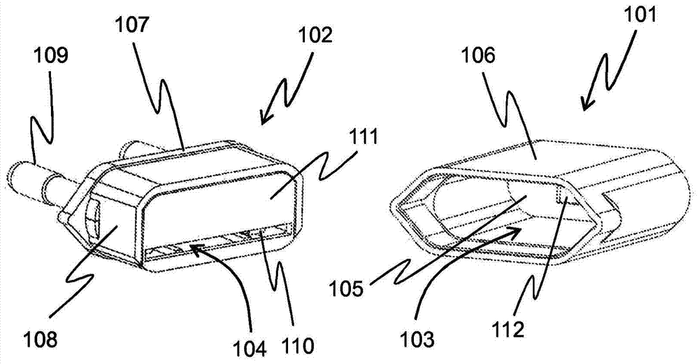
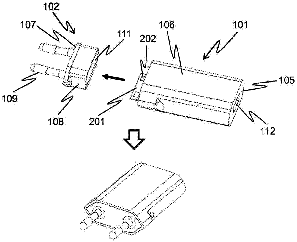
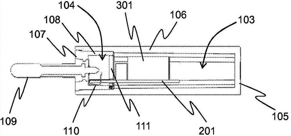
[0037] figure 1 A housing structure according to one embodiment of the invention is shown. The housing structure comprises two housing parts 101 , 102 each having a structure defining an internal cavity 103 , 104 . In order to better illustrate the internal structure of the housing, the housing parts 101, 102 are shown separated from each other.

[0038] The first housing part 101 includes a first end wall 105 and a first surrounding side wall 106 extending from the first end wall 105 . A first end wall 105 and a first surrounding side wall 106 define a first cavity 103 . Similarly, the second housing component 102 includes a second end wall 107 and a second surrounding side wall 108 extending from the second end wall 107 . A second end wall 107 and a second surrounding side wall 108 define a second cavity 104 .

[0039] When attached together, the first surroundi...


PUM

PropertyMeasurementUnit
Widthaaaaaaaaaa
Depthaaaaaaaaaa
Depthaaaaaaaaaa

Abstract

The present invention provides a housing structure for an electrical device, which housing structure comprises a first housing part (101) having a first end wall (105) and a first surrounding side wall (106) extending from the first end wall (105), the first end wall (105) and the first surrounding side wall (106) defining a first cavity (103). The housing structure also comprises a second housing part (102) connected to the first housing part (101), the second housing part (102) comprising a second end wall (107) opposing the first end wall (105), and connector pins (109) passing through the second end wall (107). The second housing part (102) further comprises a second surrounding side wall (108) extending from the second end wall (107) into the first cavity (103), the second end wall (107) and the second surrounding side wall (108) defining a second cavity (104) that is partly closed by a third end wall (111).

Description

technical field [0001] The invention relates to a housing structure for an electrical device according to the preambles of the appended independent claims. The invention also relates to an electrical device comprising such a housing structure. Background technique [0002] Electrical equipment needs to operate safely in any environment without causing danger to its users. Electrical equipment should also always be safely disconnected in the event of a malfunction. [0003] Electrical equipment is usually well protected against electric shock to the user during normal operation of the equipment, and in the event of an electrical fault such as a short circuit. However, if the mechanical structure of electrical equipment is damaged, the risk of electric shock will increase significantly. For example, if the housing of an electrical device becomes detached from the body of the device or is broken into multiple pieces by mechanical shock, live electrical contacts and wires may...

Claims


Application Information

Patent Timeline
IPC IPC(8): H01R13/44H01R31/06H05K5/00
CPCH01R24/68H01R13/6658H01R13/502H01R13/447H01R13/665H01R31/065H05K5/02
Inventor J·霍卡宁
Owner SALCOMP OYJ
Learn More