Method for strip head correction in continuous rolling strip threading process

A strip and head technology, which is applied in the field of strip head deviation correction in the continuous rolling strip threading process, and can solve problems such as poor correction effect of the strip head

Active Publication Date: 2015-01-28
GUANGXI LIUZHOU YINHAI ALUMINUM IND
View PDF6 Cites 16 Cited by
  • Summary
  • Abstract
  • Description
  • Claims
  • Application Information

AI Technical Summary

Problems solved by technology

[0003] The purpose of the present invention is to provide a method for correcting the deviation of the head of the strip in the process of continuous rolling and

Method used


Image

  • Method for strip head correction in continuous rolling strip threading process
  • Method for strip head correction in continuous rolling strip threading process
  • Method for strip head correction in continuous rolling strip threading process

Examples


Embodiment 1

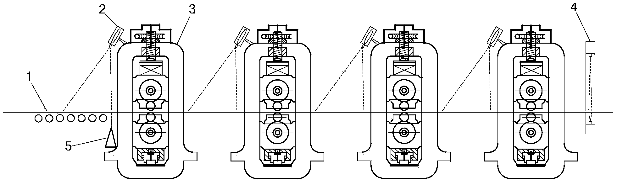
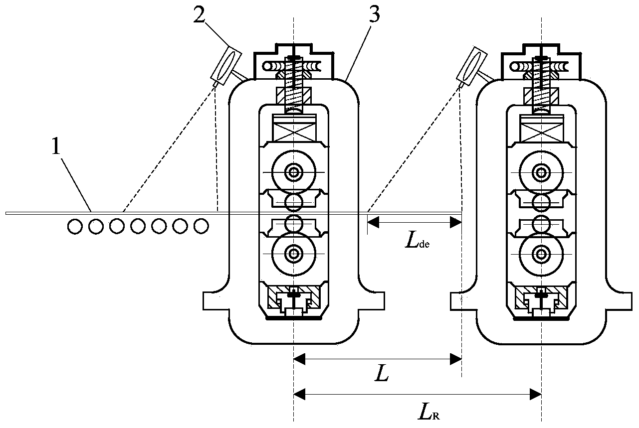
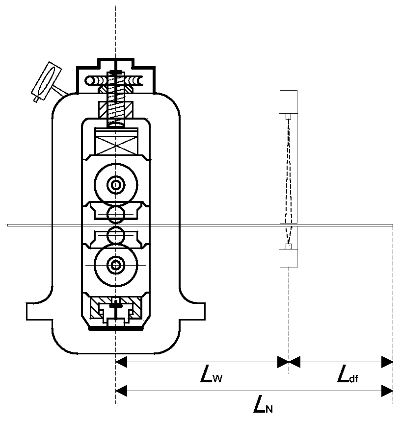
[0141] Since the distance between the roll gaps between the racks generally does not exceed 6000 mm, care should be taken to ensure the length of the sampling area L when installing the camera de Not greater than 4000 mm, preferably L de = 2500 mm. The image is digitized by a high-speed image data acquisition card and sent to the computer. As the object of rolling piece size identification, the computer processes the digital image, extracts the edge information of the strip head, and obtains the final planar size of the rolled piece. When the rolled piece passes through the detection area between the racks, the signal of the head of the strip processed by the PLC system is used to control the industrial CCD camera to collect an image and send it to the computer for image acquisition and data processing. Assume that the total number of stands in the tandem mill is 4. The roller transmission motor end of the frame is equipped with a speed measuring encoder, and the real-time s...


PUM


Abstract

The invention discloses a method for strip head correction in the continuous rolling strip threading process and relates to the technical field of metal pressure processing. The method comprises a step (A) of setting sampling time points of strip heads reaching each detection position; a step (B) of judging and calculating the strip head deflection degree and the deflection direction by performing imaging collection and processing on edge curves on the two sides of the strip heads when the strip heads reach the detection position of a current to-be-rolled machine frame in the strip threading process; a step (C) of performing on-line adjustment on roll gap differences of the double sides of a currently rolled machine frame; a step (D) of presetting roll gap differences of the double sides of a follow-up machine frame; a step (E) of repeating the step (C) and the step (D) until a profile gaugemeter detects the strip heads, and performing on-line adjustment on roll gap differences of the double sides of a finished product machine frame through the profile curves of two side edges of the strip heads detected by the multichannel profile gaugemeter. According to the method, the deflection of the heads in continuous rolling strip threading process of the strips can be timely found and adjusted so as to avoid yield reduction or strip threading failure caused by the deflection.

Description

technical field [0001] The invention relates to the technical field of metal pressure processing, in particular to a method for correcting the deviation of the strip head during continuous rolling strip threading. Background technique [0002] During the continuous rolling process of plate and strip, due to the influence of asymmetric factors or the side bending of the incoming material, the strip head may be deflected when threading the strip, which is one of the main factors affecting the product yield and coiling quality. First, in severe cases, it may even directly lead to the failure of belt threading, resulting in the scrapping of the entire rolled piece or damage to the equipment. At present, the domestic calendering factory still stays at the level of manual control on the head deviation correction of the strip. Operators often adjust the difference between the roll gaps on both sides based on experience and visual inspection of the deviation degree of the head of th...

Claims


Application Information

Patent Timeline
IPC IPC(8): B21B39/14B21B38/02B21B37/58
Inventor 许磊刘栩周滨蒋婷李江宇
Owner GUANGXI LIUZHOU YINHAI ALUMINUM IND
Why Eureka
Try Eureka