Automatic photoelectric control binding machine for travel book
What is Al technical title?
Al technical title is built by PatSnap Al team. It summarizes the technical point description of the patent document.
An automatic binding and photoelectric control technology, applied in binding and other directions, can solve the problems of uneven signatures, uncompacted signatures, skewed paper, etc., and achieve the effect of less follow-up work, convenient operation and high work efficiency
Inactive Publication Date: 2015-01-28
成都怡云科技有限公司
View PDF6 Cites 4 Cited by
Summary
Abstract
Description
Claims
Application Information
AI Technical Summary
This helps you quickly interpret patents by identifying the three key elements:
Problems solved by technology
Method used
Benefits of technology
Problems solved by technology
Some problems that may occur when loading the signature bucket, such as: paper skew, curling, tearing, signatures are not compacted when folding, not crisp, signatures are not aligned, etc., these problems will make the paper becomes very difficult, thereby slowing down the stapler considerably, so an automatic stapler should be invented
Method used
Image
Click on the blue label to locate the original text in one second.
Reading with bidirectional positioning of images and text.
Examples
Embodiment Construction
[0013] The present invention will be further described below in conjunction with accompanying drawing:
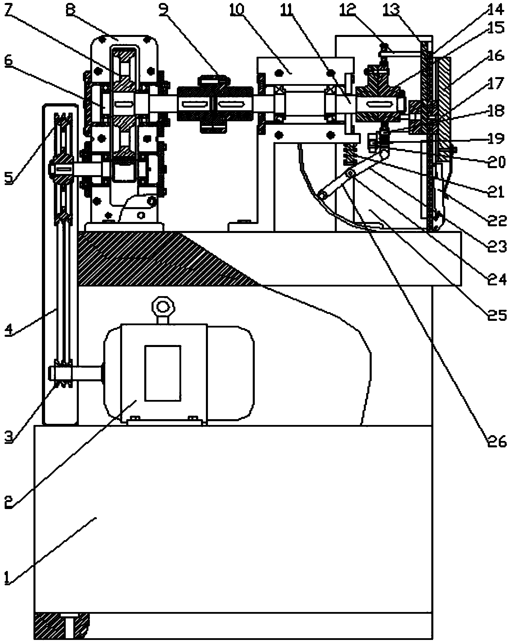
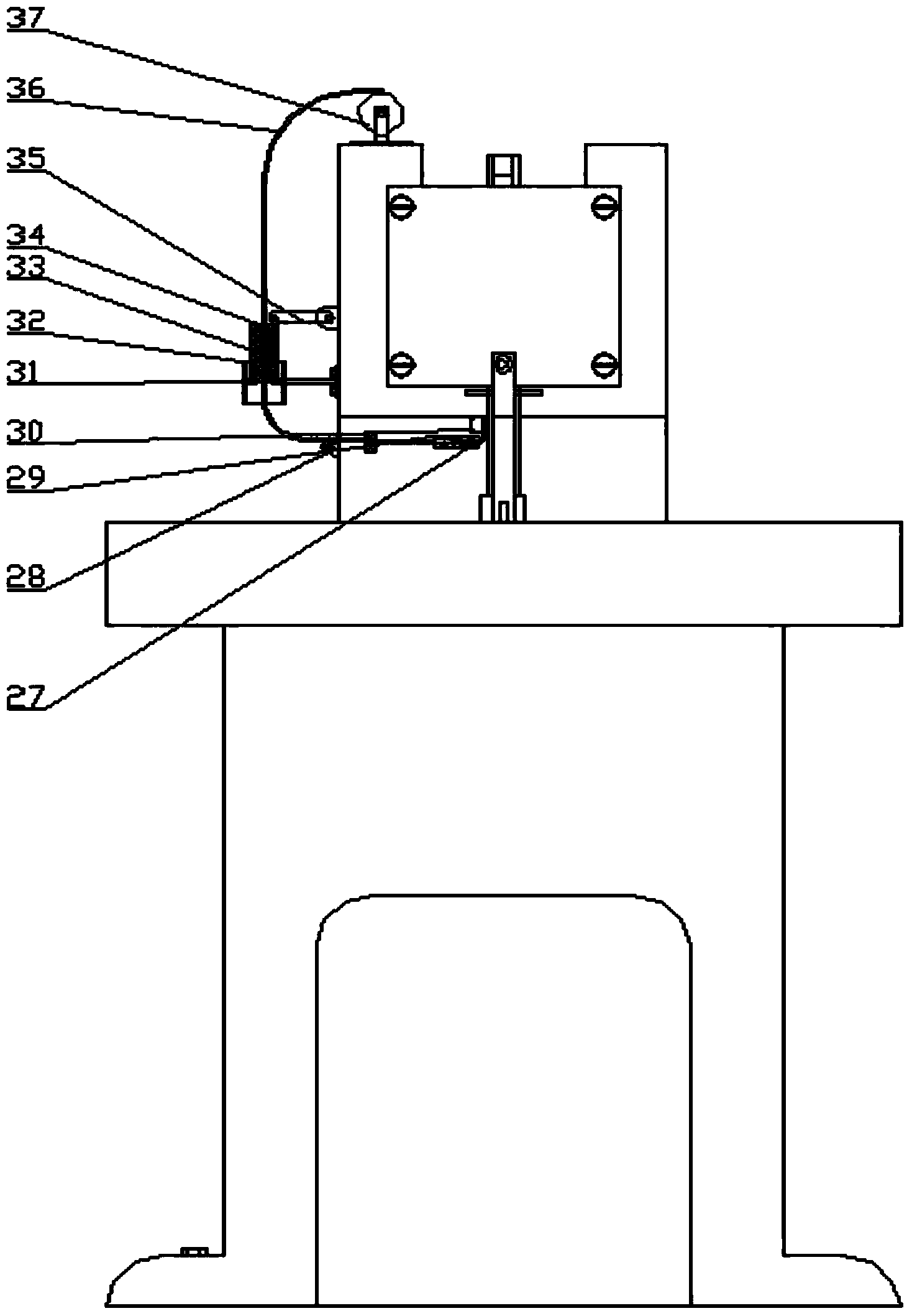
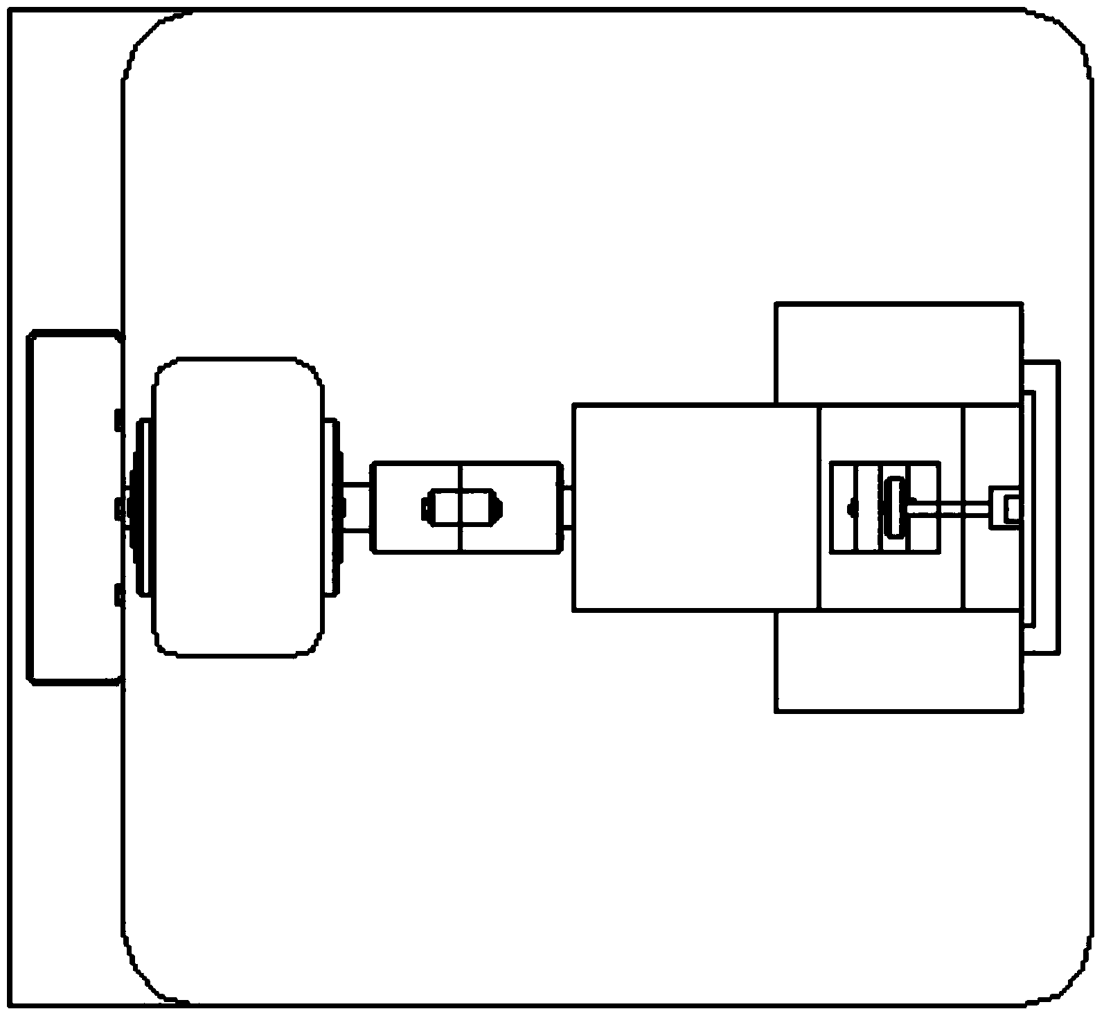
[0014] Such as figure 1 , figure 2 as well as image 3 Shown, a kind of photoelectric control stroke book automatic binding machine, comprises motor 2, small pulley 3, big pulley, big gear 5, working shaft 11, binding slider 13, forming slider, cam 15, gland 16, Slider 17, roller shaft 18, cut-off roller 19, cut-off roller shaft 20, connecting rod 23, hinge 24, box body 25, swing bar 26, photoelectric induction cutter 27, roller 28, wire guide hole 29, slide block 30, Frame 31, connecting rod 2. 32, iron wire 36, photoelectric wire feed wheel 37; Described motor 2 is arranged on support 1 top; Use V-belt 4 to connect between described big pulley 5 and described small pulley 3; The large gear 7 is arranged on the large gear shaft 6; the working shaft 11 is connected with the large gear shaft 6 using a coupling 9; the end of the working shaft 11 is provided with a cam 15;...
PUM
Abstract
The invention discloses an automatic photoelectric control binding machine for travel books. The automatic photoelectric control binding machine for the travel books is characterized in that the automatic photoelectric control binding machine comprises a motor, a small pulley, a large pulley, a large gear, a working shaft, a binding slider, a forming slider, a cam, a gland, a slider, a roller shaft, a cutting wheel, a cutting wheel shaft, a connecting rod, a hinge, a box, an oscillating bar, a photoelectric sensor cutter, a wheel, a guide wire hole, a slider, a frame, a connecting rod, an iron wire and a photoelectric wire feeding wheel; the gland is arranged on the outer edge of a machine base; a roller shaft is disposed between the cam and the binding slider; the cutting wheel is mounted on the roller shaft; a tongue-shaped guide block is arranged on the lower portion of the binding slider; a spring is disposed above the connecting rod; the oscillating bar is mounted at the rear end of the connected rod; the iron wire penetrates through a sleeve, the edge of which is provided with a chuck and a spring chuck; the photoelectric sensor cutter is arranged on the upper portion of the rear end edge of the guide wire hole; the photoelectric wire feeding wheel is mounted above the frame.
Description
technical field [0001] The invention belongs to the field of optoelectronic mechanical equipment, and in particular relates to an automatic book binding machine with photoelectric control stroke. Background technique [0002] Currently, bookbinding involves transporting the folded paper to the collating table, accounting for 80% of the time in the binding process. Some problems that may occur when loading the signature bucket, such as: paper skew, curling, tearing, signatures are not compacted when folding, not crisp, signatures are not aligned, etc., these problems will make the paper becomes very difficult, thereby slowing down the stapler considerably, so an automatic stapler should be invented. The application number is: 02143455.7 discloses a book binding device and a binding method. The binding device is a binding device that bonds the back surface of a stack of papers with the central part of a cover page. The device includes a paper supply A device, a thickness det...
Claims
Application Information
Patent Timeline
Application Date:The date an application was filed.
Publication Date:The date a patent or application was officially published.
First Publication Date:The earliest publication date of a patent with the same application number.
Issue Date:Publication date of the patent grant document.
PCT Entry Date:The Entry date of PCT National Phase.
Estimated Expiry Date:The statutory expiry date of a patent right according to the Patent Law, and it is the longest term of protection that the patent right can achieve without the termination of the patent right due to other reasons(Term extension factor has been taken into account ).
Invalid Date:Actual expiry date is based on effective date or publication date of legal transaction data of invalid patent.