Novel self-loading and-unloading mechanism

A new type of self-loading and unloading technology, which is applied in the direction of transportation, packaging, garbage storage, etc., can solve the problems of weak clamping, complicated hydraulic system, complicated control operation, etc., and achieve the effect of ensuring cleanliness, reducing leakage points, and simplifying the hydraulic system

Active Publication Date: 2015-01-28
ZHONGQI COMML VEHICLE CO LTD HANGZHOU
View PDF10 Cites 12 Cited by
  • Summary
  • Abstract
  • Description
  • Claims
  • Application Information

AI Technical Summary

Problems solved by technology

[0006] The invention solves the defects that the existing garbage truck needs a special oil cylinder to clamp the garbage can, which causes complex hydraulic system and complicated control operation, and provides a new type of self-loading and unloading mechanism, which does not need a special oil cylinder to clamp, and can be clamped by the barrel Clamping is achieved by the rotation of the cam, which saves the oil cylinder, simplifies the hydraulic system, and reduces the leakage point of the hydraulic system
[0007] The present invention also solves the defects that the existing garbage truck prevents the garbage can from falling by setting a baffle, which causes weak clamping, the garbage can is easy to shake, and causes the garbage to fall and pollute the ground, and provides a new type of self-loading and unloading mechanism. During the lifting process, the clamping force is generated, and the clamping is appropriate, and the garbage can will not shake when it is turned over, so that the garbage can be completely poured into the garbage bucket to prevent pollution of the surrounding ground

Method used


Image

  • Novel self-loading and-unloading mechanism
  • Novel self-loading and-unloading mechanism
  • Novel self-loading and-unloading mechanism

Examples


Embodiment

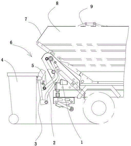
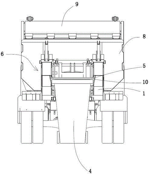
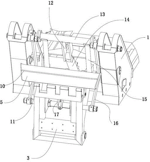
[0028] Embodiment: a kind of novel self-loading and unloading mechanism 6 (see attached figure 1 attached figure 2 attached image 3 ), including a bracket 1 fixed at the rear of the vehicle. A hydraulic cylinder 14 is hinged on the bracket. Two rotating arms 2 with different linear lengths are also hinged on the bracket. The ends of the two rotating arms are hinged with a base 3. The base is used for hanging bucket.

[0029]The short pivoting arm of straight line length is to adjust pivoting arm 16, and the long pivoting arm of straight line length is turning over pivoting arm 15. Wherein the adjusting arm is above the flipping arm, that is, the position where the adjusting arm is hinged to the base is above the base, the position where the flipping arm is hinged to the base is below the base, and the position where the adjusting arm is hinged to the bracket is higher than that of the flipping arm. The position hinged with the bracket is high. The two pivoting arms are f...


PUM


Abstract

The invention relates to a novel self-loading and unloading mechanism. The novel self-loading mechanism comprises a support fixed on a vehicle, wherein two rotating arms with different linear lengths are hinged between the support and a base; a hydraulic cylinder is hinged between one of the rotating arms and the support; the two rotating arms are matched with each other to drive the base to overturn; a garbage bin hanging plate is arranged on the base; a garbage bin pressing plate is further hinged to the base; a rotary push rod is fixed on the garbage bin pressing plate; a garbage bin hanging cam is fixed on the rotating arm corresponding to the rotary push rod; the garbage bin hanging cam is matched with the rotary push rod to drive the garbage bin pressing plate to rotate and is matched with the garbage bin hanging plate to achieve clamping operation. The garbage bin hanging cam is matched with the rotary push rod to enable the garbage bin pressing plate to rotate around a hinge position so as to achieve mutual approach or departure between the garbage bin pressing plate and the garbage bin hanging plate; the garbage bin pressing plate approaches the garbage bin hanging plate to clamp the upper edge of a garbage bin; in the rotating and lifting process of the base, a clamping force always exists, so that the garbage bin does not swing and the steadiness of the garbage bin is improved.

Description

technical field [0001] The invention relates to a self-loading and unloading mechanism, in particular to a novel self-loading and unloading mechanism which can complete loading and unloading without a clamping oil cylinder. Background technique [0002] The rear-loading self-loading garbage truck is a special vehicle for urban sanitation that efficiently collects and transfers garbage. In the process of garbage collection and transfer, it can prevent secondary pollution caused by leakage along the way. It is an ideal equipment for urban sanitation work to collect domestic barreled garbage in alleys, alleys and other environments where it is difficult for garbage trucks to collect garbage. There are two main types of self-loading garbage trucks currently on the market: side-loading and rear-loading. Side-mounted self-loading garbage trucks are more used to collect food waste. In addition, some rear-loading self-loading garbage trucks designed by some peer manufacturers in th...

Claims


Application Information

Patent Timeline
Patent Type & Authority Applications(China)
IPC IPC(8): B65F3/04
CPCB65F3/04B65F3/14
Inventor 糜龙翔倪媛媛郑刚杨广生
Owner ZHONGQI COMML VEHICLE CO LTD HANGZHOU
Why Eureka
Try Eureka