Swing type stamping mould

A stamping die and swing type technology, applied in the field of swing type stamping die, can solve the problem of large mold structure and other problems, and achieve the effect of improving production quality, stable structure and increasing safety.

Inactive Publication Date: 2018-08-03
BAIC MOTOR CORP LTD
View PDF8 Cites 1 Cited by
  • Summary
  • Abstract
  • Description
  • Claims
  • Application Information

AI Technical Summary

Problems solved by technology

[0005] In view of this, the present invention proposes a swing type stamping die, which aims to solve the technical problem of large die structure volume in the prior art

Method used


Image

  • Swing type stamping mould
  • Swing type stamping mould
  • Swing type stamping mould

Examples


Embodiment Construction

[0036] Exemplary embodiments of the present disclosure will be described in more detail below with reference to the accompanying drawings. Although exemplary embodiments of the present disclosure are shown in the drawings, it should be understood that the present disclosure may be embodied in various forms and should not be limited by the embodiments set forth herein. Rather, these embodiments are provided for more thorough understanding of the present disclosure and to fully convey the scope of the present disclosure to those skilled in the art. It should be noted that, in the case of no conflict, the embodiments of the present invention and the features in the embodiments can be combined with each other. The present invention will be described in detail below with reference to the accompanying drawings and examples.

[0037] It should be noted that, in the description of the present invention, terms such as "upper", "lower", "left", "right", "inner", "outer" and other indic...


PUM


Abstract

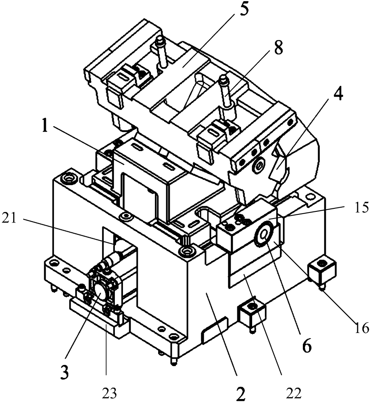
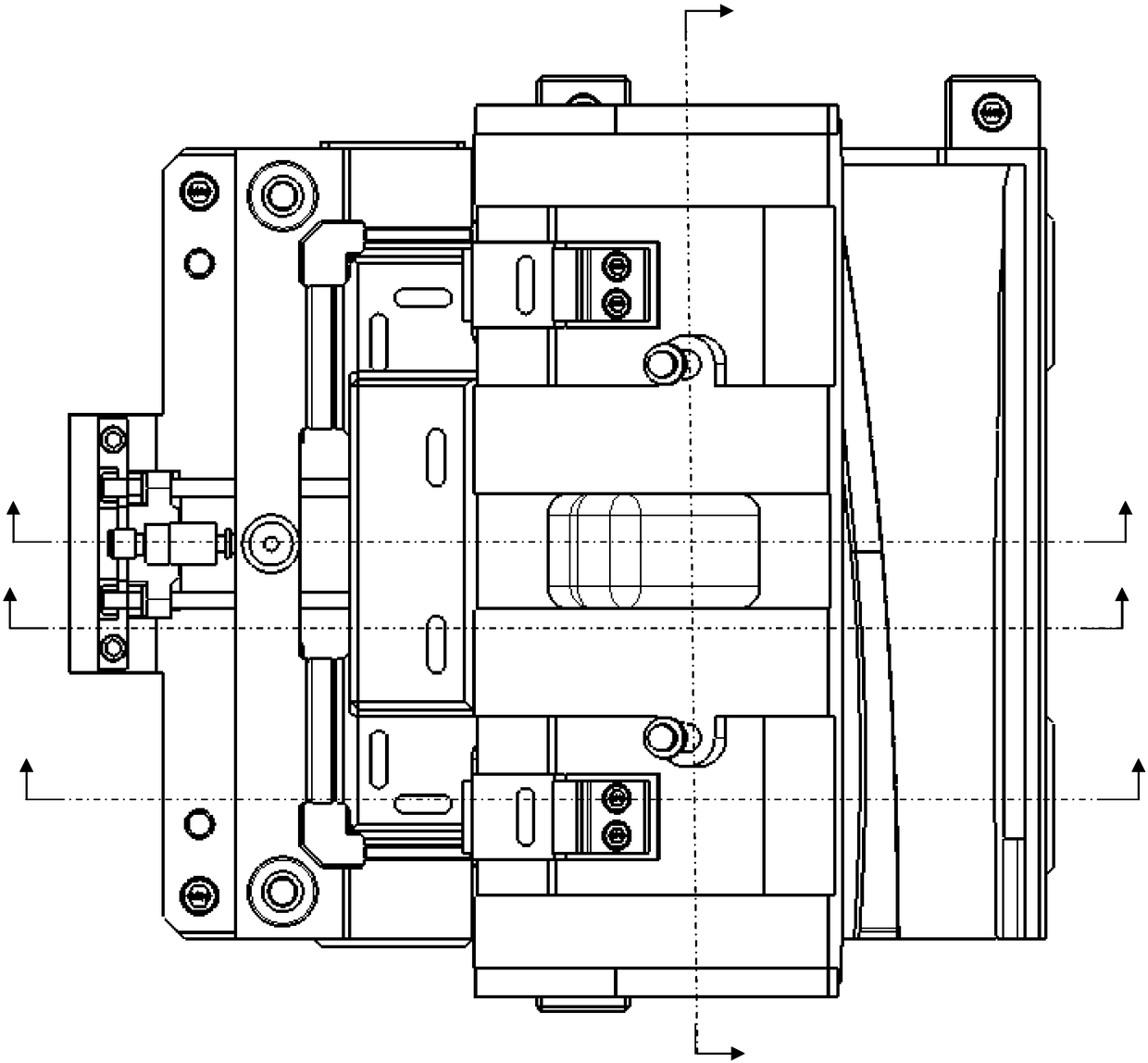
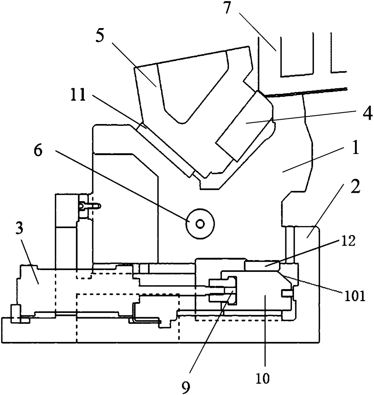
The invention discloses a swing type stamping mould. The swing type stamping mould comprises a lower mould swing slide block, a swing slide block base, an upper mould slide block, swing shafts and a drive device, wherein the swing slide block base is of a box body structure; the drive device is arranged at the bottommost end of the swing slide block base for driving the lower mould swing slide block to rotate around the swing shafts; the lower mould swing slide block is arranged above the drive device for placing a product; the two swing shafts are separately fixed at the two ends of the lowermould swing slide block; and the upper mould side block is arranged above the lower mould swing slide block for reshaping the product. Compared with the prior art, the swing type stamping mould has the beneficial effects that: the swing shafts are arranged at the two sides of the lower mould swing slide block, and an air cylinder and an inclined wedge structure drive the lower mould swing slide block to rotate around the swing shaft, so that in comparison with a conventional push type stamping mould, the swing type stamping mould has the advantages of being simpler in structure, small in occupied space, reducing cost, being low in mould closing height, and being capable of improving stamping production efficiency.

Description

technical field [0001] The invention relates to the field of automobile manufacturing, in particular to a swing stamping die. Background technique [0002] At present, the side shaping of the fender in the overlapping area with the front door is formed by stamping with a push-type wedge structure. The traditional push-type wedge structure is stamped and formed. The working process and principle of the stamping die are as follows: [0003] The punch slider is in the return position before working. When the mold is working, the upper mold drives the driving block to move downward, and the upper wedge guide plate pushes the cart to move along its slide rail, and the upper wedge guide plate pushes the punch slider to the In the working position, the workpiece is attached to the slider of the punch, the pressing core starts pressing down, and then the upper mold continues to move downward, and the upper mold slider realizes side shaping through the shaping knife installed on it. ...

Claims


Application Information

Patent Timeline
Patent Type & Authority Applications(China)
IPC IPC(8): B21D37/10B21D37/12B21D53/88
CPCB21D37/10B21D37/12B21D53/88
Inventor 艾树良赵水龙年雪山
Owner BAIC MOTOR CORP LTD
Why Eureka
Try Eureka