A horizontal annealing furnace anti-swing device

A technology of horizontal annealing furnace and anti-swing device, which is applied in vacuum annealing furnace and other fields, which can solve the problems of poor thermal insulation performance, wear of vacuum furnace liner, and surface wear of parts, so as to improve the quality of annealing treatment and improve efficiency , The effect of strengthening the stiffness

Active Publication Date: 2016-05-25
江苏昱昊机械有限公司
View PDF7 Cites 0 Cited by
  • Summary
  • Abstract
  • Description
  • Claims
  • Application Information

AI Technical Summary

Problems solved by technology

[0002] Existing vacuum annealing furnaces, especially horizontal vacuum annealing furnaces, due to the requirements of sealing performance and heat preservation performance, are divided into two sides of the furnace outer cover, which has the advantage of saving space. The sealing position is at the top of the vacuum furnace, and it is a butt joint. When the vacuum annealing furnace is used, it is inconvenient to observe and plug the leakage in time. Time to get high quality annealed parts
[0003] Therefore, we try to use a horizontal vacuum annealing furnace, especially in the heating and annealing process of the vacuum furnace for titanium and titanium alloy blanks in a vacuum state, using a vacuum annealing furnace separated from the left and right, which will lead to A large swing will be generated, which will cause wear on the inner tank of the vacuum furnace, and will also cause frictional damage to the parts that are placed in the vacuum furnace to be processed or have been processed, causing the surface wear of some parts and reducing their quality.

Method used


Image

  • A horizontal annealing furnace anti-swing device
  • A horizontal annealing furnace anti-swing device
  • A horizontal annealing furnace anti-swing device

Examples


Embodiment Construction

[0014] In order to deepen the understanding of the present invention, the present invention will be further described below in conjunction with the accompanying drawings and embodiments, which are only used to explain the present invention and do not limit the protection scope of the present invention.

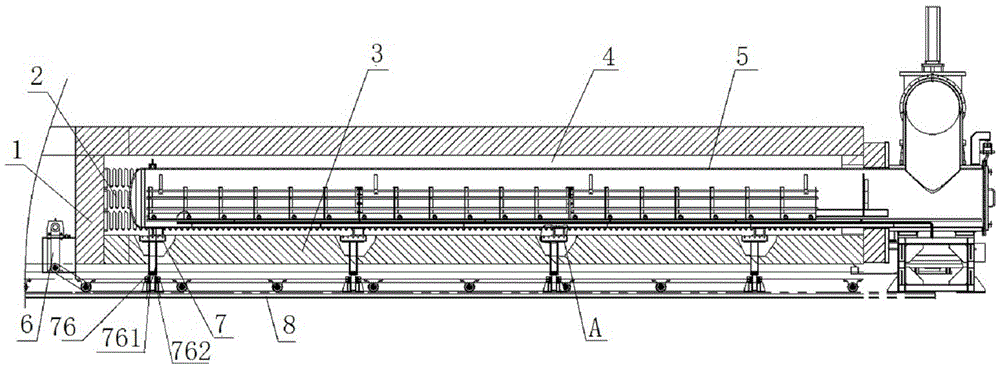
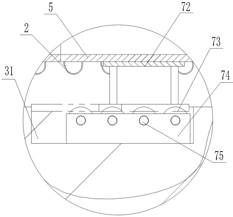
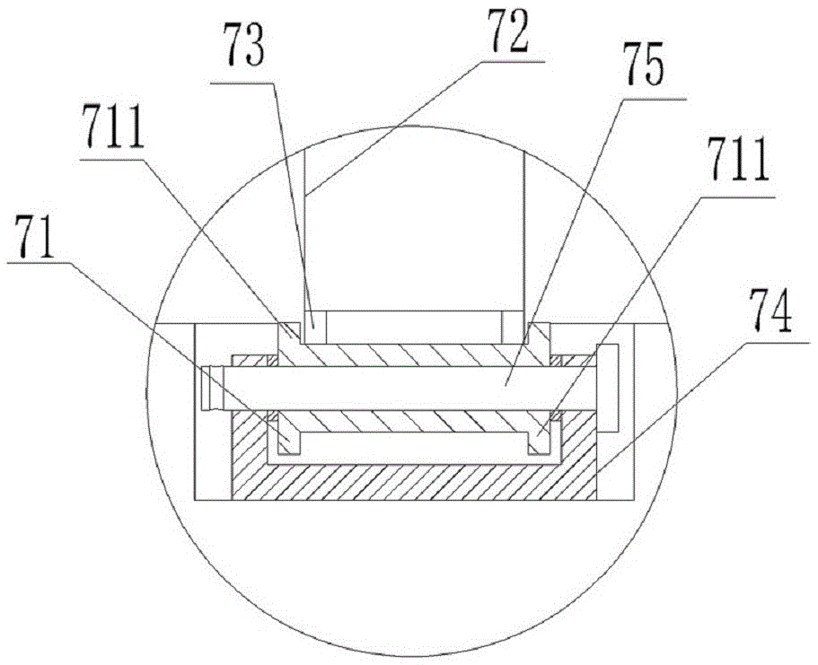
[0015] Such as figure 1 and image 3 As shown, a horizontal annealing furnace anti-swing device, the vacuum annealing furnace includes an outer cover 1, a heating element 2, a running part 3 and a furnace liner 5, and the furnace liner 5 is connected between the outer cover 1 and the running part 3, thereby forming Vacuum chamber 4; the running part 3 is connected to the track device 8 through the transmission device 6 and moves left and right; the heating element 2 is connected in the vacuum chamber 4 to heat the vacuum furnace, and at least one set of anti-swing devices is symmetrically connected to the running part 3 of the annealing furnace Each anti-swing device 7 includ...


PUM


Abstract

The invention discloses an anti-swing device for a horizontal annealing furnace. The vacuum annealing furnace comprises an outer cover, a heating element, a travelling part and a furnace liner, wherein the furnace liner is connected between the outer cover and the traveling part; the traveling part is connected on a track device to move left and right by virtue of a transmission device; the heating element is connected in a vacuum cavity to heat the vacuum furnace, at least one group of anti-swing devices are symmetrically connected on two sides of the travelling part of the annealing furnace, each anti-swing device comprises a connecting part, at least one roller and a bracket, and the upper end of each connecting part is attached to the bottom of the furnace liner while the lower end of each connecting part is pressed on the at least one roller; the bracket is used for fixedly connecting the roller on the traveling part; a double-lug bush is further connected between each roller and a shaft, and the connecting part is pressed between two lugs of the double-lug bush. According to the anti-swing device disclosed by the invention, the left and right separated horizontal annealing furnace is reduced or avoided, so that the annealing treatment quality and the annealing treatment efficiency of parts which are placed in the annealing furnace are improved.

Description

technical field [0001] The invention relates to the field of vacuum annealing furnace and technology, in particular to an anti-swing device for a horizontal annealing furnace. Background technique [0002] Existing vacuum annealing furnaces, especially horizontal vacuum annealing furnaces, due to the requirements of sealing performance and heat preservation performance, are divided into two sides of the furnace cover, which has the advantage of saving space. The sealing position is at the top of the vacuum furnace, and it is a butt joint. When the vacuum annealing furnace is used, it is inconvenient to observe and timely plug the leakage. Time to get high quality annealed parts. [0003] Therefore, we try to use a horizontal vacuum annealing furnace, especially in the heating annealing process of the vacuum furnace for titanium and titanium alloy blanks in a vacuum state, using a vacuum annealing furnace separated from the left and right, which will lead to A larger swing ...

Claims


Application Information

Patent Timeline
Patent Type & Authority Patents(China)
IPC IPC(8): C21D1/26C21D1/773
CPCC21D1/26C21D1/773
Inventor 陈金祥
Owner 江苏昱昊机械有限公司
Why Eureka
Try Eureka