Locking-type glass door lock

A glass door lock, locking technology, applied in the direction of building locks, buildings, building structures, etc., can solve the problems of deformation and fracture of positioning columns, loss of anti-theft function, poor strength, etc.

Inactive Publication Date: 2015-01-28
林荣炽
View PDF5 Cites 0 Cited by
  • Summary
  • Abstract
  • Description
  • Claims
  • Application Information

AI Technical Summary

Problems solved by technology

After the lock is locked, when the lock tongue is impacted by a large external force, the strength will be poor, and the positioning post will be deformed and broken. When the external pressure applied to the lock tongue is greater than t...

Method used


Image

  • Locking-type glass door lock
  • Locking-type glass door lock
  • Locking-type glass door lock

Examples


Embodiment 1

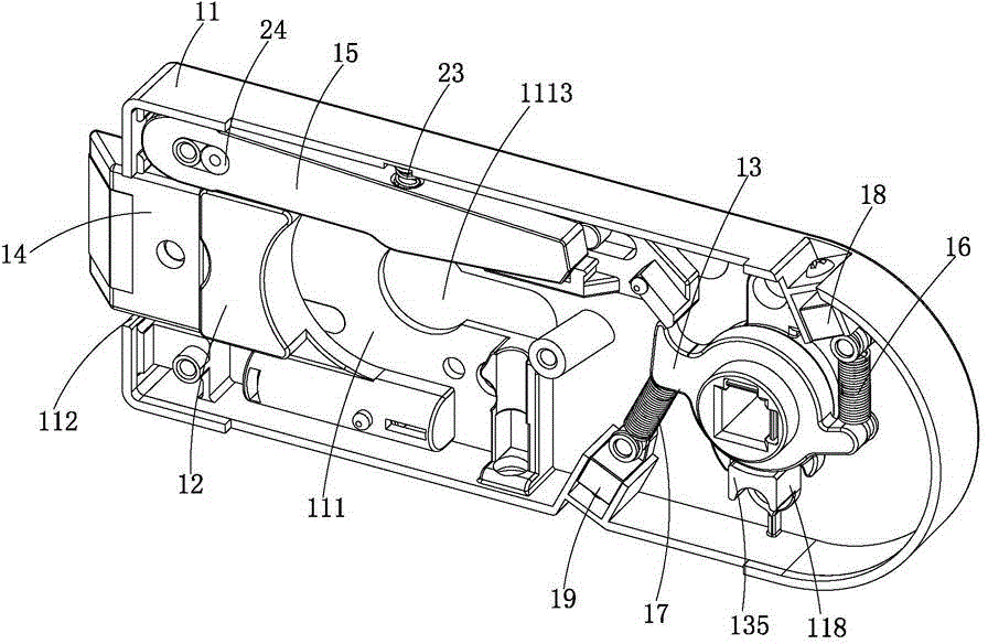
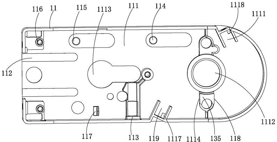
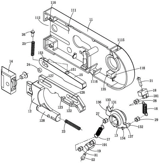
[0042] see Figure 1-Figure 8 As shown, a locking type glass door lock is mainly composed of a lock body 11, a gland 32, a deadbolt movement mechanism installed in the lock body 11, a torsion wheel 13 and its first tension spring reset device, and the second tension spring reset. Device, positioning rod 15 and lock tube 41 form. The dead bolt movement mechanism comprises dead bolt 14, slide block 12, the 1st positioning post 114 and the 2nd positioning post 115, and dead bolt 14 is fixed on the front end of slide block 12, and the first guide groove 126 of slide block 12 and the 2nd guide groove 127 are matched and slidably connected with the first positioning column 114 and the second positioning column 115 fixed in the lock body 11 respectively, and the dead bolt 14 is located at the front end portion of the lock body 11 at the edge lock opening 112 . The shaft of the twist wheel 13 is installed in the first shaft hole 1112 on the lock body 11 and the second shaft hole 321 ...

Embodiment 2

[0061] see Figure 9 , Figure 10As shown, the structure of the lockable glass door lock of this embodiment is basically the same as that of the lockable glass door lock of Embodiment 1, the difference is that the first guide groove 126 and the second guide groove of the slider 12 Between 127 there is also a seventh positioning post 120 recessed in the plane of the main body of the slider 12 and a pipe-shaped groove 1213 recessed in the main body of the slider 12 , the seventh positioning post 120 is located in the center of the pipe portion of the pipe-shaped recess 1213 . The front end of the seventh positioning column 120 is provided with a fifth overlapping surface 1202 , and the rear end of the seventh positioning column 120 is provided with a sixth overlapping surface 1201 .

[0062] The 8th positioning post 150 that protrudes is provided with the 8th positioning post 150 that protrudes in the center of the positioning rod 15 main body between the 5th positioning post 1...

Embodiment 3

[0072] see Figure 11 , Figure 12 As shown, the structure of the lockable glass door lock of this embodiment is basically the same as that of the lockable glass door lock of Embodiment 2, except that the sixth overlapping surface 1201 of the seventh positioning post 120 of the slider 12 The 3rd semicircle positioning groove 1203 is added in the lower part of the locating bar 15, and the 3rd front 1502 lower part of the 8th positioning column 150 of the positioning rod 15 is additionally provided with the 3rd semicircle positioning column 1503. catch. In the closed state, the third semicircular positioning column 1503 is hooked with the third semicircular positioning groove 1203 to prevent the positioning rod 15 from dislocating and moving outward when the deadbolt 14 is subjected to a strong external force and loses the positioning and locking function.

[0073] In general, the lock-type glass door lock of embodiment 3 has the most powerful locking function, followed by the...


PUM


Abstract

The invention discloses a locking-type glass door lock. An upper swing arm, a lower swing arm, a convex hook and a convex limiting column are arranged on a torsion wheel; the upper swing arm and the lower swing arm are symmetric to each other; a first tension spring resetting device is arranged behind the lower part of the upper swing arm; a second tension spring resetting device is arranged above the lower swing arm; a guide groove and a positioning column are arranged at the upper part of a sliding block; the positioning column of the sliding block is in matched superposed contact with a positioning column of a positioning rod; a fixed hole in the front end of the positioning rod is movably connected with a fixed column of a lock body; an arc-shaped collision area of the positioning rod is in sliding contact with a lock liner boss; a spring resetting device is arranged between the positioning rod and the surrounding edge of the lock body; the guide groove in the upper part of the sliding block is slidably connected with the positioning column of the lock body; a slider is arranged at the rear end of the sliding block and is in sliding contact connection with the convex hook of the torsion wheel; a spring resetting device is further arranged at the lower part of the sliding block. According to the door lock, the degree of friction probably formed between a shaft of the torsion wheel and a matched shaft hole can be minimized, the service life of the door lock is greatly prolonged, the locking firmness of the door lock can be greatly improved, and therefore the burglary prevention capacity of the door lock is improved.

Description

technical field [0001] The invention relates to the technical field of glass door locks, in particular to a locking type glass door lock. Background technique [0002] This kind of glass door lock is widely used in anti-theft locks in public places, and it has the functions of lock in, lock out and lock out. This kind of lock has a purely mechanical structure and is usually used in public places, resulting in very frequent opening and closing of the lock. The torsion wheel of the glass door lock only uses a pressure spring or tension spring for resetting the torsion wheel. Under the action of force, the shaft of the torsion wheel and the shaft hole are eccentric and severely worn and elliptical, and the spring will also fatigue and break in advance. Time Since the force point of the tension spring is concentrated on the apex of the shackle at both ends of the spring, at this time, friction caused by tension will occur between the spring fixing column on the torsion wheel an...

Claims


Application Information

Patent Timeline
IPC IPC(8): E05B65/02E05B15/00
Inventor 林荣炽
Owner 林荣炽
Why Eureka
Try Eureka