
Condenser microphone unit and condenser microphone

a condenser microphone and microphone technology, applied in the direction of electrostatic transducer microphones, microphone structural associations, plane diaphragms, etc., can solve the problems of not teaching the configuration to accurately arrange the configuration components, and the characteristic of the microphone, so as to achieve the effect of improving assembly accuracy and effectively suppressing eccentricity

Active Publication Date: 2017-06-15
AUDIO-TECHNICA
View PDF6 Cites 11 Cited by
  • Summary
  • Abstract
  • Description
  • Claims
  • Application Information

AI Technical Summary

Benefits of technology

The invention is a condenser microphone unit that reduces eccentricity and improves assembly accuracy. This results in a more accurate and reliable signal for recording. The invention can be used in a variety of applications such as audio recorders and communication devices.

Problems solved by technology

In the condenser microphone unit, when the diaphragm, the fixed electrode, and the other component are not positioned in the unit holder with accuracy, an individual difference in characteristics of the microphone occurs due to eccentricity between components, further leading to breakdown.
However, the condenser microphone of Japanese Patent No. 4926663 does not teach a configuration to accurately arrange the configuration components of the microphone unit in the baffle.

Method used


Image

  • Condenser microphone unit and condenser microphone
  • Condenser microphone unit and condenser microphone
  • Condenser microphone unit and condenser microphone

Examples


Embodiment Construction

[0022]Hereinafter, a condenser microphone according to an embodiment of the present invention will be described in detail with reference to the drawings.

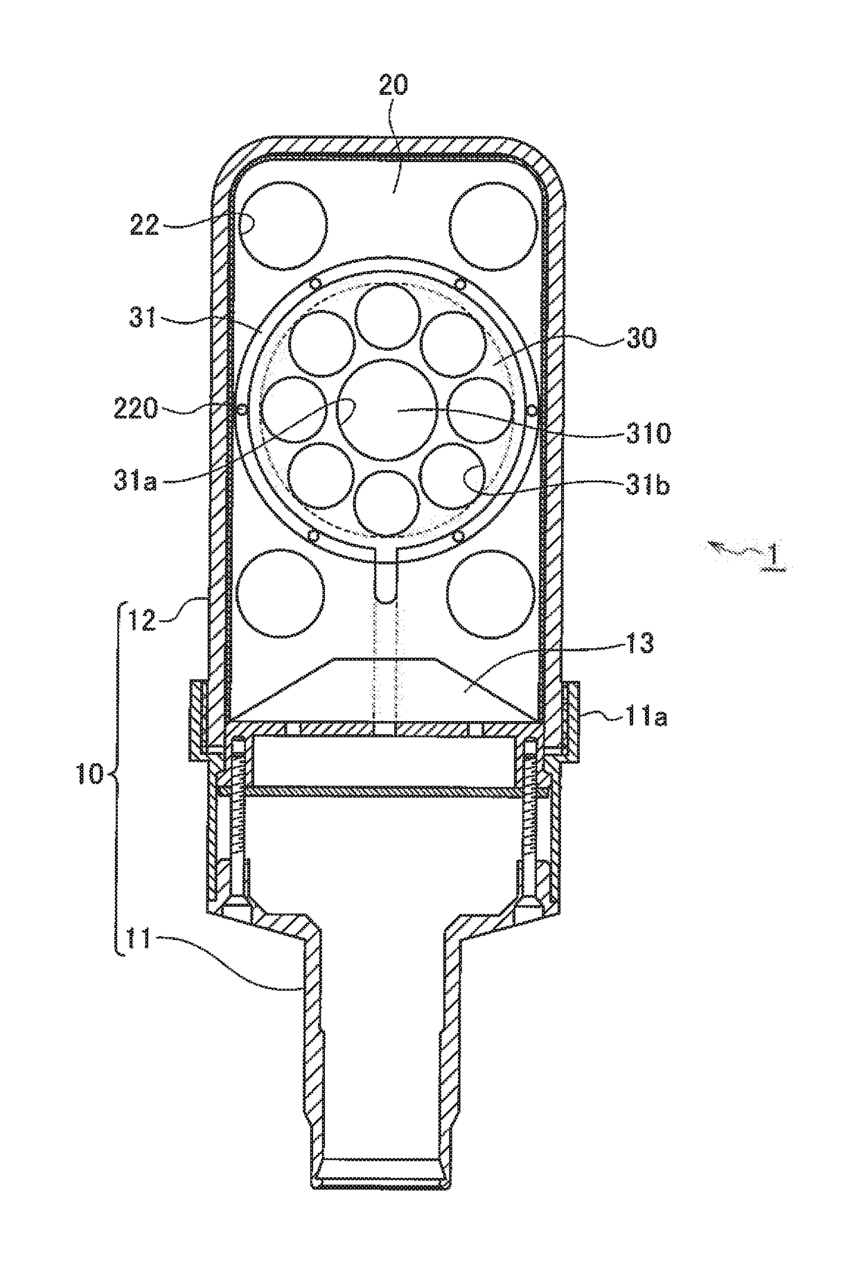
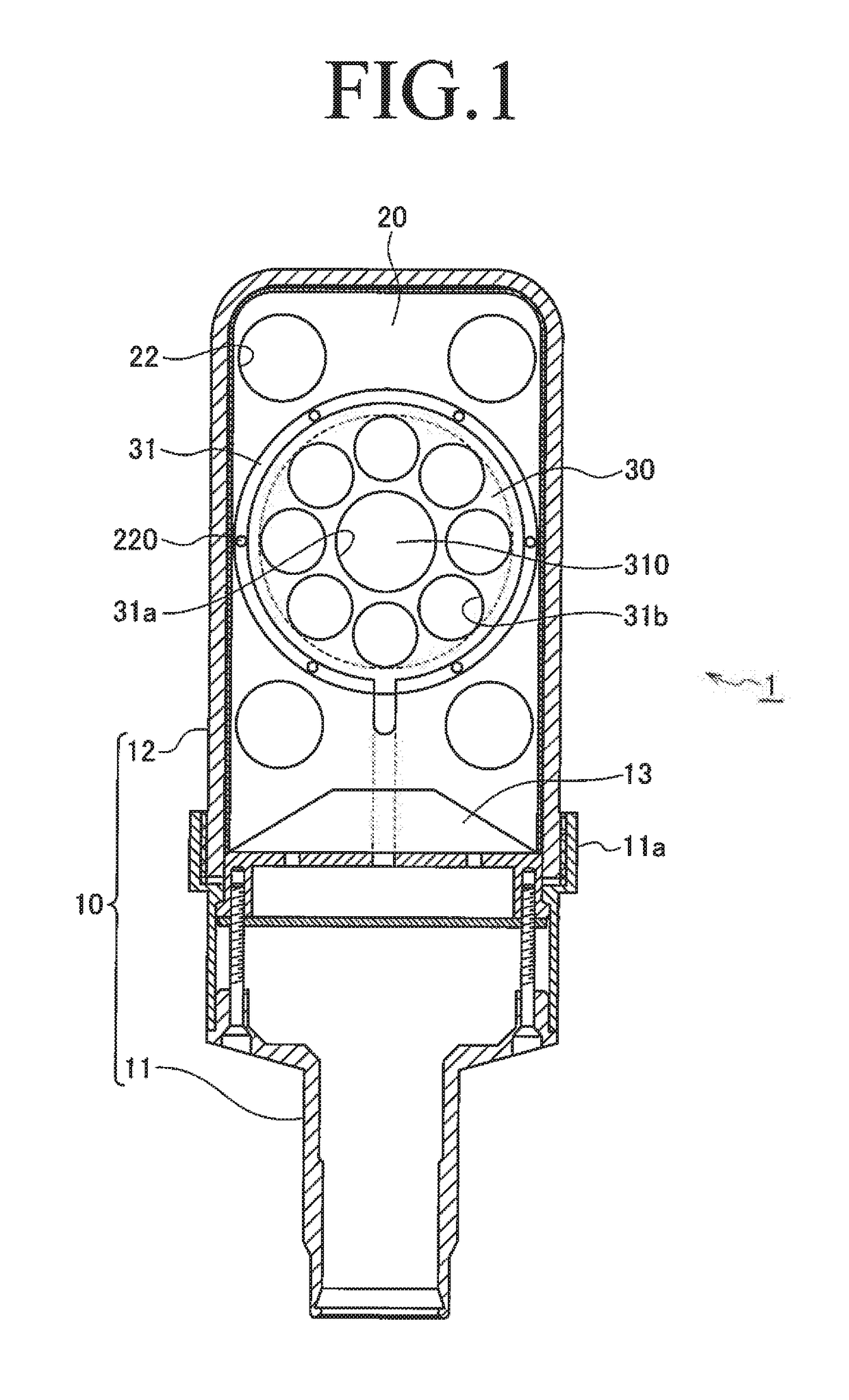
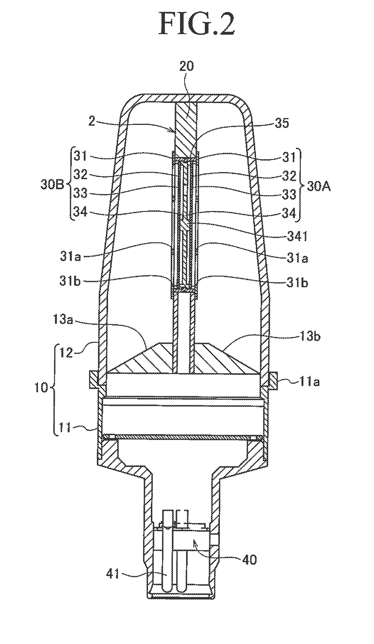
[0023]As illustrated in FIGS. 1 and 2, a condenser microphone 1 of an embodiment includes, as a housing 10, a lower case 11 to be attached to a microphone stand and an upper case 12 in which a microphone unit 2 is accommodated.

[0024]The upper case 12 has a cup-like external shape, and is attached to the lower case 11 to be sandwiched between a base portion 13 provided at one end side (an upper side in FIG. 1) of the lower case 11 and a latch portion 11a formed into a ring shape on a side surface of the lower case 11. A connector base 40 to which a plurality of connector pins 41 is attached is arranged at the other end side (a lower side in FIG. 2) of the lower case 11. One end side of the connector pin 41 is connected to a signal line from a microphone element 30. The other end side of the connector pin 41 is connected with an exter...


PUM


Abstract

Provided is a condenser microphone unit that prevents eccentricity as much as possible and achieves improvement of assembly accuracy. A condenser microphone unit including a diaphragm that vibrates upon receiving a sound wave and made by a plurality of configuration components that are assembled, the condenser microphone unit includes a base member including an opening portion to which the plurality of configuration components is attached, and an adjustment member having an outer diameter corresponding to a diameter of the opening portion, and mounted to a side surface of one or more components accommodated in the opening portion, of the plurality of configuration components. The adjustment member is a frame body exhibiting an annular shape and including a notch portion notched to have a pair of end portions, and is fixed in the opening portion in a state of being mounted to the side surface of the one or more components.

Description

BACKGROUND[0001]Technical Field[0002]The present invention relates to a condenser microphone unit and a condenser microphone.[0003]Related Art[0004]A condenser microphone unit includes a film-like diaphragm that vibrates upon receiving a sound wave, a fixed electrode (may also be referred to as “back plate”) arranged to face the diaphragm with a predetermined gap, and another component that fixes and holds the diaphragm and the fixed electrode in a unit holder. In the condenser microphone unit having the structure, the diaphragm and the fixed electrode configure a capacitor, and when the diaphragm vibrates upon receiving a sound wave, capacitance of the capacitor is changed, and thus the change of the capacitance is output as change of an electrical signal.[0005]In the condenser microphone unit, when the diaphragm, the fixed electrode, and the other component are not positioned in the unit holder with accuracy, an individual difference in characteristics of the microphone occurs due...

Claims


Application Information

Patent Timeline
IPC IPC(8): H04R19/04H04R7/04H04R1/04H04R7/18
CPCH04R19/04H04R1/04H04R7/04H04R7/18H04R1/025
Inventor AKINO, HIROSHI
Owner AUDIO-TECHNICA
Learn More