Electric shuttle valve of cam mechanism

A technology of electric shuttle valve and cam mechanism, which is applied in the direction of valve details, multi-way valves, valve devices, etc., can solve the problems of inability to meet the cleanliness requirements of the aerospace gas system, the decrease of sealing performance, and the wear of gaskets, etc., and achieve simple structure , reduce the driving torque, reduce the effect of frictional resistance

Active Publication Date: 2015-01-28
BEIJING SATELLITE MFG FACTORY
View PDF6 Cites 2 Cited by
  • Summary
  • Abstract
  • Description
  • Claims
  • Application Information

AI Technical Summary

Problems solved by technology

At the same time, after long-term operation, the gasket will be worn, the sealing performance will be reduced, and excess will be generated at the same time, so it cannot meet the cleanliness requirements of the aerospace gas system
[0004] In the environmental control and life protection system, it is nece

Method used


Image

  • Electric shuttle valve of cam mechanism
  • Electric shuttle valve of cam mechanism
  • Electric shuttle valve of cam mechanism

Examples


Embodiment Construction

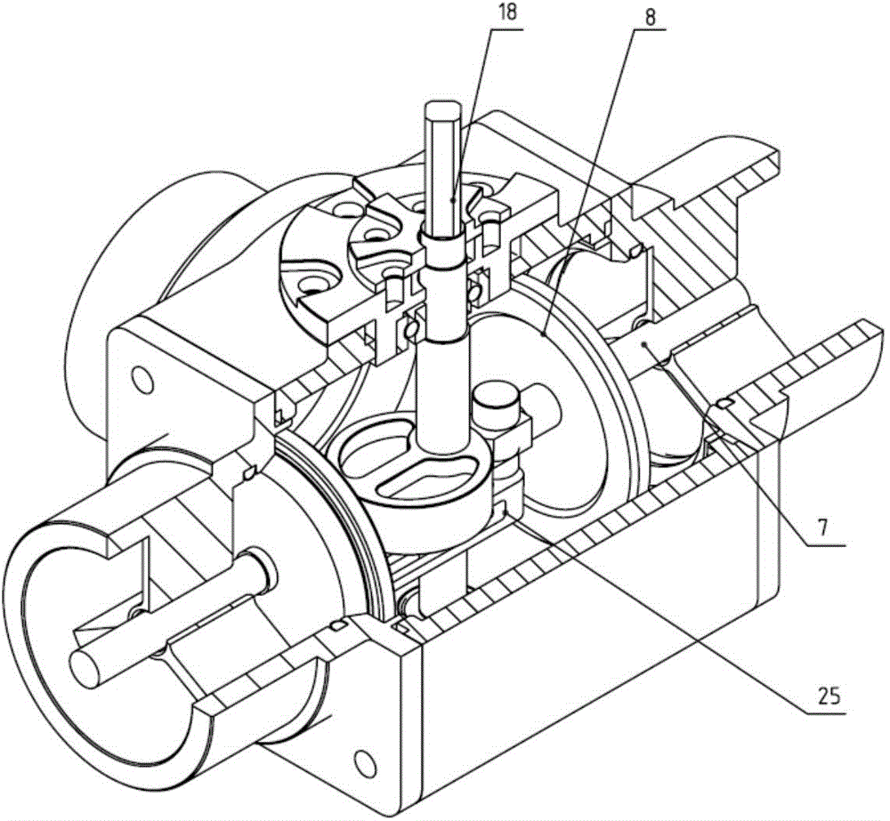
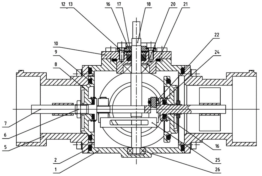
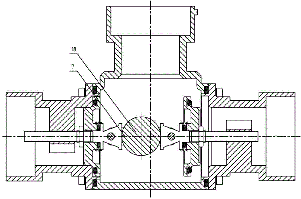
[0019] Such as figure 1 As shown, the electric shuttle valve of the present invention consists of a three-way valve body 1, a first sealing ring 2, a flange end cover 5, an M8 thin nut 6, a guide rod 7, a valve core 8, a second sealing ring 9, and a sealing gland 10. First sealing packing 12, second sealing packing 13, disc spring 16, upper gland 17, valve stem 18, first bearing 20, third sealing ring 21, fixing ring 22, bellows 24, connecting frame 25, The second bearing 26 is formed. The flange end cover 5 and the first sealing ring 2 are installed on the three-way valve body 1 (left and right); the sealing gland 10, the second sealing ring 21 and the first bearing 20 are installed on the three-way valve body 1 (top); the first sealing packing 12, the second sealing packing 13, the disc spring 16, and the upper gland 17 are installed on the three-way valve body 1 (top, between the sealing gland 10 and the first bearing 20); bellows 24 is welded as one with guide rod 7, spo...


PUM


Abstract

The invention relates to an electric shuttle valve of a cam mechanism. A three-way valve body (1) is of a two-position two-way structure, and three holes distributed in an inverted T shape are formed in the three-way valve body (1) and form an inlet and outlets. Flange end covers (5) are fixedly connected to the outlets, and a sealing gland (10) is fixedly connected to the inlet. Valve cores (8) are positioned at the connecting positions of the flange end covers (5) and the three-way valve body (1), and guide rods (7) penetrate through the valve cores (8) and are integrally and fixedly connected with the valve cores (8). A valve rod (18) penetrates through the sealing gland (10), enters into the three-way valve body (1) and is assembled in the three-way valve body (1) through a bearing. An eccentric circular cam is arranged in the middle of the valve rod (18). One end, positioned in the three-way valve body (1), of each guide rod (7) is fixedly connected with a connecting frame (25) through a fixed ring (22), so that the two guide rods (7) is butted against the cam and form an integral link structure. The cam is driven to rotate through the rotation of the valve rod (18), so that the valve cores (8) on one side are far away from the flange end covers (5), and the inlet is communicated with the outlets on one side.

Description

technical field [0001] The invention relates to an electric valve, which can be used for adsorption and analysis of a regenerative CO2 removal system and a regenerative trace harmful gas removal system of an aerospace environmental control and life protection system. Background technique [0002] The aerospace environmental control and life support system provides the air needed for life support for the personnel on the spacecraft, and at the same time purifies and absorbs the exhaust gas generated by astronauts in space and the trace amount of harmful gas generated by internal devices. The system includes various physical and chemical reaction devices and various manual and electric valves, which have been working throughout the entire life cycle of the spacecraft, and each work process is completed by switching the corresponding valves to complete the switching of the gas system. [0003] At present, ball valves are mostly used in manual selection valves, which have simple...

Claims


Application Information

Patent Timeline
IPC IPC(8): F16K11/044F16K41/02
CPCF16K11/044F16K31/52416F16K41/02
Inventor 李咚咚杜国飞盛君刘净瑜韩建超姚旗邹丹赵健范洪涛付振东谢文
Owner BEIJING SATELLITE MFG FACTORY
Why Eureka
Try Eureka